Page 51 of 262
6. Trip computer mode/set")
1. Headlight/turn signal switch
2. Instrument brightness control switch
3. Driver supplemental air bag/Horn
4. Meters/gauges
5. Cruise control main/set switch
(if so equipped)6. Trip computer mode/setting switch
7. Windshield wiper/washer switch
8. Center ventilator
9. Cup holder
10. Passenger supplemental air bag
11. Side ventilator12. VDC (Vehicle dynamic control) OFF switch
or TCS (Traction control system) OFF
switch (if so equipped)
13. Soft top operating switch (for Roadster
models)
14. Fuel filler lid opener switch
15. Hood lock release handle
16. Fuse box
17. Tilting steering wheel lock lever
18. Ignition switch/steering lock
19. Navigation system* or Instrument pocket
20. Rear window (and outside mirror) defroster
switch
21. Heater/air conditioner control
22. Audio system/Clock
23. Heated seat switch (if so equipped)
24. Hazard warning flasher switch
25. Tray
26. Power outlet
*: Refer to the separate Navigation System
Owner’s Manual.
SIC2268
INSTRUMENT PANEL2-2
Instruments and controls
�
04.5.17/Z33-D/V5.0
�
Page 57 of 262

TRIP COMPUTERThe display of the trip computer is situated in the
triple meter. When the ignition switch is turned
to ON, the display scrolls all the modes of the
trip computer and then shows the mode chosen
before the ignition switch is turned OFF.Switches for the trip computer are located on
the side of the combination meter panel. To
operate the trip computer, press the side of the
switches as shown above.
�A: Trip computer mode switch
�B: Trip computer setting switch
When the ignition switch is turned to ON, modes
of the trip computer can be selected by pressing
the trip computer mode switch
�A.
Each time the mode switch
�A
is pressed, the
display will change as follows:
Speed indicator→Outside air temperature
(ICY)→Distance to empty (dte)→Average fuelconsumption and speed→Elapsed time and
trip odometer→Stopwatch→Tire pressure
indicator (PSI) (if so equipped)→Up-shift indi-
cator setting (for M/T models)→Speed indica-
tor
Speed indicator (mph or km/h)The vehicle speed is displayed in MPH or km/h
while driving.
The speed indicator in the trip computer
indicates the reference speed. The actual
speed indicated by the speedometer (com-
bination meter) may differ from the one in
the trip computer.Outside air temperature
(ICY—°For°C)The outside air temperature is displayed in °F or
°C in the range of −22 to 131°F (−30 to 55°C).
The outside air temperature mode includes a low
temperature warning feature: below 37°F (3°C),
the outside air temperature mode is automati-
cally selected and the ICY indicator will illumi-
nate in order to draw the driver’s attention. Press
the mode switch
�A
if you wish to return to the
mode that was selected before the warning
occurred. The ICY indicator will continue blink-
ing as long as the temperature remains below
39°F (4°C).
SIC2234
SIC1957
2-8
Instruments and controls
�
04.5.17/Z33-D/V5.0
�
Page 73 of 262

headlight switch to the
position for full
illumination when driving at night.
If the parking brake is applied before the engine
is started, the daytime running lights do not
illuminate. The daytime running lights illuminate
once the parking brake is released. The daytime
running lights will remain on until the ignition
switch is turned off.
WARNING
When the daytime running light system
is active, tail lights on your vehicle are
not on. It is necessary at dusk to turn on
your headlights. Failure to do so could
cause an accident injuring yourself and
others.
TURN SIGNAL SWITCH�1
Turn signal
Move the lever up or down to signal the turning
direction. When the turn is completed, the turn
signals cancel automatically.�2
Lane change signal
To indicate a lane change, move the lever up or
down to the point where lights begin flashing.
INSTRUMENT BRIGHTNESS
CONTROLThe instrument brightness control operates
when the light switch is in the
or
position and the ignition switch is in the
ON position.
To adjust the brightness of instrument panel
lights, press the control switches located on the
left side of the meter panel. Pressing the upper
switch�A
will brighten the lights. The lower
switch
�B
will dim the lights. Repeatedly press-
ing the lower switch will turn the lights off.
SIC1963
SIC2236
2-24
Instruments and controls
�
04.5.17/Z33-D/V5.0
�
Page 76 of 262
 system ON for most
driving conditions.
When the vehicle is stuck in mud or snow, the
VDC system reduces the engine output to re-
duc")
The vehicle should be driven with the Vehicle
Dynamic Control (VDC) system ON for most
driving conditions.
When the vehicle is stuck in mud or snow, the
VDC system reduces the engine output to re-
duce wheel spin. The engine speed will be
reduced even if the accelerator is depressed to
the floor. If maximum engine power is needed to
free a stuck vehicle, turn the VDC system off.
To cancel the Vehicle Dynamic Control (VDC)
system, push the VDC OFF switch (located on
the lower side of the instrument panel) to turn off
the system. The
indicator light will come
on.Push the VDC OFF switch again or restart the
engine to turn ON the system. See “Vehicle
dynamic control (VDC) system” in the “5. Start-
ing and driving” section.
The vehicle should be driven with the Traction
Control System (TCS) ON for most driving
conditions.
To cancel the Traction Control System (TCS),
push the TCS OFF switch (located on the lower
side of the instrument panel). The
indicator
light will come on. Push it again or restart the
engine to turn the system back on.
See “Traction control system (TCS)” in the “5.
Starting and driving” section.
SIC1881
SIC1967
VEHICLE DYNAMIC CONTROL
(VDC) OFF SWITCH (if so
equipped)TRACTIONCONTROL SYSTEM
(TCS) OFF SWITCH (if so
equipped)
Instruments and controls
2-27
�
04.5.17/Z33-D/V5.0
�
Page 86 of 262

45 seconds after the ignition key is turned to the
OFF position.
Depending on the environment or driving
conditions, the auto reverse function may
be activated if an impact or load similar to
something being caught in the window
occurs.
WARNING
There are some small distances imme-
diately before the closed position which
cannot be detected. Make sure that all
passengers have their hands, etc., in-
side the vehicle before closing the win-
dow.Automatic window lowering (Roadster
models)When the soft top operating switch is pressed,
the power windows will automatically be low-
ered completely. The windows do not rise auto-
matically after the soft top open/close operation
is completed. Use the power window switches
to raise them.
AUTOMATIC ADJUSTING
FUNCTION
CAUTION
When the battery cable is removed from
the battery terminal, do not close either
of the front doors. The automatic win-
dow adjusting function will not work,
and the side roof panel/top side rail
may be damaged.
The power window has an automatic adjusting
function. When the door is being opened, the
window is automatically lowered slightly to avoid
contact between the window and the side roof
panel/top side rail. When the door is closed, the
window is automatically raised slightly.
INTERIORThe interior light has a two-position switch. (
�A:
DOOR,
�B: OFF)
When the switch is in the DOOR position, the
light will illuminate when a door is opened.
The light will stay on for about 30 seconds when:
�The doors are unlocked by the keyfob, a key
or the power door lock switch while all doors
are closed.
�The driver’s door is opened and then closed
while the key is removed from the ignition
switch.
SIC1980A
Coupe models
INTERIOR LIGHTS
Instruments and controls
2-37
�
04.5.17/Z33-D/V5.0
�
Page 102 of 262
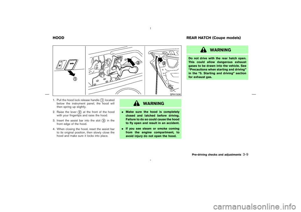
1. Pull the hood lock release handle
�1
located
below the instrument panel; the hood will
then spring up slightly.
2. Raise the lever
�2
at the front of the hood
with your fingertips and raise the hood.
3. Insert the assist bar into the slot
�3
in the
front edge of the hood.
4. When closing the hood, reset the assist bar
to its original position, then slowly close the
hood and make sure it locks into place.
WARNING
�Make sure the hood is completely
closed and latched before driving.
Failure to do so could cause the hood
to fly open and result in an accident.
�If you see steam or smoke coming
from the engine compartment, to
avoid injury do not open the hood.
WARNING
Do not drive with the rear hatch open.
This could allow dangerous exhaust
gases to be drawn into the vehicle. See
“Precautions when starting and driving”
in the “5. Starting and driving” section
for exhaust gas.
SPA1506
HOODREAR HATCH (Coupe models)
Pre-driving checks and adjustments
3-9
�
04.5.17/Z33-D/V5.0
�
Page 106 of 262
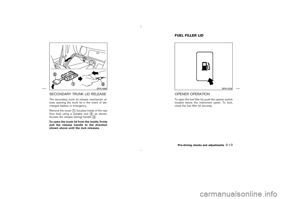
SECONDARY TRUNK LID RELEASEThe secondary trunk lid release mechanism al-
lows opening the trunk lid in the event of dis-
charged battery or emergency.
Remove the cover
�1
(located inside of the rear
floor box) using a suitable tool
�2
as shown.
Access the release (string) handle�3.
To open the trunk lid from the inside, firmly
pull the release handle to the direction
shown above until the lock releases.
OPENER OPERATIONTo open the fuel filler lid, push the opener switch
located below the instrument panel. To lock,
close the fuel filler lid securely.
SPA1688
SPA1508
FUEL FILLER LIDPre-driving checks and adjustments
3-13
�
04.5.17/Z33-D/V5.0
�
Page 111 of 262
Foldable outside mirrorsFold the outside mirror by pushing it toward the
rear of the vehicle.1. Soft top operating switch
2. Soft top indicator light (on the combination
meter)
3. Top side rail
4. Top latch lever
5. Soft top
6. Top storage lid
7. Trunk lid
8. Rear window
9. Rear section of the top
BEFORE OPERATING THE TOPThe soft top of your 350Z Roadster is electrically
operated. You can fully open or close the top
only by pressing the operating switch (on the
lower side of the instrument panel).
The soft top operating switch must be operated
under all of the following conditions:
�When the foot brake pedal is depressed.
�When the vehicle is stopped.
�When the engine is running.
IC0565
SPA1689
Interior/exterior view
SOFT TOP OPERATION(Roadster
models)
3-18
Pre-driving checks and adjustments
�
04.5.17/Z33-D/V5.0
�

3. Top side rail
4. Top")