Page 357 of 435

356 Practical hintsReplacing bulbs�
Insert the new bulb in the socket so
that the base is in the recess on the
lower left.
�
Attach the retaining springs.
�
Insert connector7 into the bulb.
�
Press cover3 onto the housing until
the tab engages.Replacing halogen high beam bulbs
�
Switch off the lights.
�
Open the hood (
�page 272).
�
Press the tab on cover2 and remove
cover.
�
Pull connector 6 off of the bulb.
�
Apply pressure on the bulb contacts
from above until the bulb releases from
the retaining springs.
�
Remove bulb.
�
Insert the new bulb in the socket with
the marking facing upward.
�
Press the bulb upward on the contacts
until it engages in the retaining springs.
�
Insert connector6 onto the bulb.
�
Press cover2 onto the housing until
the tab engages.Front turn signal lamp bulb
�
Switch off the lights.
�
Open the hood (
�page 272).
�
Twist bulb socket8 counterclockwise
and pull out.
�
Gently push bulb into socket, turn
counterclockwise and remove.
�
Insert new bulb in socket, push in and
twist clockwise.
�
Reinstall bulb socket in lamp and twist
clockwise until it engages.
��
Page 358 of 435
357 Practical hints
Replacing bulbs
Parking and standing lamp bulb�
Switch off the lights.
�
Open the hood (
�page 272).
�
Press the tab on cover2 and remove
cover.
�
Pull out the bulb socket5 with the
bulb.
�
Pull the bulb out of the bulb socket.
�
Insert a new bulb in the socket.
�
Reinstall the bulb socket.
�
Press cover2 onto the housing until
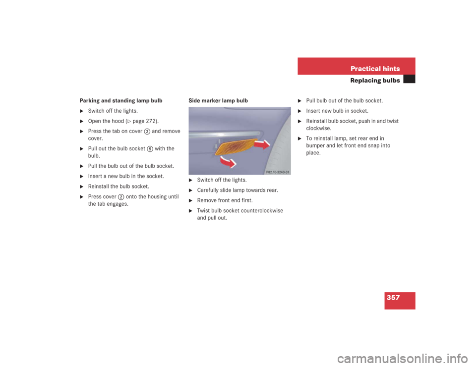
the tab engages.Side marker lamp bulb
�
Switch off the lights.
�
Carefully slide lamp towards rear.
�
Remove front end first.
�
Twist bulb socket counterclockwise
and pull out.
�
Pull bulb out of the bulb socket.
�
Insert new bulb in socket.
�
Reinstall bulb socket, push in and twist
clockwise.
�
To reinstall lamp, set rear end in
bumper and let front end snap into
place.
Page 359 of 435
358 Practical hintsReplacing bulbsReplacing bulbs for rear lamps
Tail lamp assemblies
1Turn signal lamp (white socket)
2Tail, parking, standing, and side marker
lamp (red socket)
3Tail lamp, rear fog lamp (red socket)
4Backup lamp (black socket)
�
Switch off the lights.
�
Open trunk.
�
Turn the catch, and move the trim to
the side.
�
Turn bulb socket counterclockwise and
pull out.
�
Gently twist bulb counterclockwise and
pull out of bulb holder.
�
Insert new bulb into the holder and turn
it clockwise.
�
Reinstall bulb socket.
The bulb socket should audibly click.
�
Replace trim and secure with lock. License plate lamp
1Screws
�
Switch off the lights.
�
Loosen both screws1 and remove
lamp.
�
Replace the tubular lamp and reinstall
it.
�
Retighten the screws.
Page 364 of 435
363 Practical hints
Flat tire
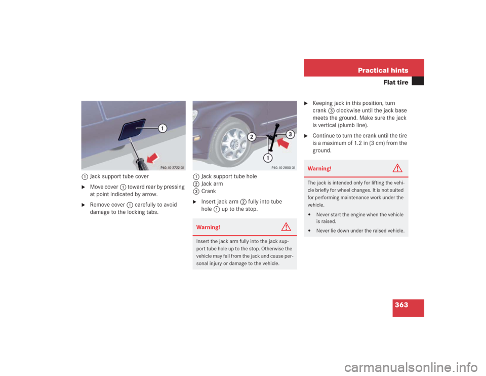
1Jack support tube cover�
Move cover1 toward rear by pressing
at point indicated by arrow.
�
Remove cover1 carefully to avoid
damage to the locking tabs.1Jack support tube hole
2Jack arm
3Crank
�
Insert jack arm2 fully into tube
hole1 up to the stop.
�
Keeping jack in this position, turn
crank3 clockwise until the jack base
meets the ground. Make sure the jack
is vertical (plumb line).
�
Continue to turn the crank until the tire
is a maximum of 1.2 in (3 cm) from the
ground.
Warning!
G
Insert the jack arm fully into the jack sup-
port tube hole up to the stop. Otherwise the
vehicle may fall from the jack and cause per-
sonal injury or damage to the vehicle.
Warning!
G
The jack is intended only for lifting the vehi-
cle briefly for wheel changes. It is not suited
for performing maintenance work under the
vehicle.�
Never start the engine when the vehicle
is raised.
�
Never lie down under the raised vehicle.
Page 366 of 435

365 Practical hints
Flat tire
Lowering the vehicle�
Lower vehicle by turning crank coun-
terclockwise until vehicle is resting ful-
ly on its own weight.
�
Remove the jack.
1 - 5 Wheel bolts
�
Tighten the five wheel bolts evenly, fol-
lowing the diagonal sequence illustrat-
ed (1 to 5), until all bolts are tight.
Observe a tightening torque of
110 lb-ft (150 Nm).
�
Before storing the jack in the trunk, it
should be fully collapsed, with handle
folded in.
�
Place the wheel bolt wrench, alignment
bolt and jack back in the vehicle tool kit
in the trunk and close the covering lid.Replacing jack support tube cover
�
Slide tongue of cover under the upper
edge of the tube opening.
�
Applying even pressure, press cover
until it snaps into place. Be careful not
to damage the locking tabs or clamp
the plastic retaining strap.
Warning!
G
Have the tightening torque checked after
changing a wheel. The wheels could come
loose if they are not tightened to a torque of
110 lb-ft. (150 Nm).
!You can also screw the faulty wheel
down into the spare wheel well in the
trunk.
Do not activate the tire inflation pres-
sure monitor* until the depressurized
tire is no longer in the vehicle.
Page 369 of 435

368 Practical hintsBatteryReconnecting the battery�
Turn off all electrical consumers.
�
Connect the positive lead and fasten its
cover2.
�
Connect negative lead3.Batteries contain materials that can harm
the environment if disposed of improperly.
Large 12-volt storage batteries contain
lead. Recycling of batteries is the preferred
method of disposal. Many states require
sellers of batteries to accept old batteries
for recycling.!Never invert the terminal connections.!The battery, its filler caps and the vent
tube must always be securely installed
when the vehicle is in operation.
iThe following procedures must be car-
ried out following any interruption of
battery power (e.g. due to reconnect-
ing):�
Set the clock (see COMAND opera-
tor’s manual).
�
Resynchronize the ESP
(�page 316).
�
Resynchronize side windows
(�page 198).
�
Resynchronize sliding/pop-up roof
(�page 202).
�
Resynchronize rear seats if they
were adjusted five seconds or less
before the battery was disconnect-
ed .
Page 374 of 435

373 Practical hints
Towing the vehicle
Installing towing eye bolt
1Cover on right side of front bumper
2Cover on right side of rear bumperRemoving cover
�
Press mark on cover in direction of ar-
row.
�
Lift cover off to reveal threaded hole for
towing eye bolt.
Installing towing eye bolt
�
Take towing eye bolt and wheel wrench
out of trunk (
�page 344).
�
Screw towing eye bolt clockwise into
its stop and tighten with wheel wrench.
Removing towing eye bolt
�
Loosen towing eye bolt counterclock-
wise with wheel wrench.
�
Unscrew towing eye bolt.
�
Store towing eye bolt and wheel
wrench in trunk.
Installing cover
�
Fit cover and snap into place.
!When towing the vehicle with all wheels
on the ground, please note the follow-
ing:
With the automatic central locking acti-
vated and the SmartKey in starter
switch position2, or KEYLESS-GO*
start/stop button in position2, the ve-
hicle doors lock if the left front wheel
as well as the right rear wheel are turn-
ing at vehicle speeds of approximately
9 mph (15 km/h) or more.
Switch off the tow-away alarm
(�page 85).
To prevent the vehicle doors from lock-
ing, deactivate the automatic central
locking (
�page 106).
Towing of the vehicle should only be
done using the properly installed tow-
ing eye bolt. Never attach tow cable,
tow rope or tow rod to vehicle chassis,
frame or suspension parts.
Page 412 of 435

411 Index
Cleaning
Cup holder 301
Distronic* system sensor cover 299
Gear selector lever 301
Hard plastic trim items 301
Headlamps 177
Headliner and shelf below rear
window 301
Instrument cluster 301
Leather upholstery 302
Light alloy wheels 301
Nubuck leather upholstery 302
Parktronic* system sensor 299
Plastic and rubber parts 302
Seat belts 301
Steering wheel 301
Upholstery 302
Windows 300
Windshield 49
Wiper blades 299
Wood trims 302
Clock 23Closing
Cup holder 237
Glove box 231
Hood 273
Power windows with
KEYLESS-GO* 198
Side windows 196
Sliding/pop-up roof 199, 352
Sliding/pop-up roof with
KEYLESS-GO* 202
Sliding/pop-up roof with
SmartKey 201
Trunk lid 98
Windows 195
Windows with SmartKey 197
Closing from the inside
Trunk 100
Closing sliding/pop-up roof
In an emergency 352
Cockpit 20, 402
Cockpit management and data system
(COMAND) 402COMAND 402
COMAND* see separate operating instruc-
tions
Combination switch 128
High beam flasher 48, 128
Turn signals 47
Windshield wipers 48
Comfortable driving
Transmission program mode 170
Consumer information 399
Control and operation of radio
transmitters 266
Control system 134, 402
AUDIO menu 139
Checking oil level 274
Convenience submenu 160
Display digital speedometer 139
Distronic* menu 147
Functions 136, 138
Instrument cluster submenu 154
Lighting submenu 155
Malfunction memory menu 150

2Tail, parking, standing, and side marker
lamp (red socket)
3Tail lamp, rear fog")