Page 166 of 280
 to turn the radio on.
Band selection
Choose AM by pressing the AM butto")
6-46
Interior Comfort
Au di o S ys t em
Form No. 8S15-EA-03G
�Operating the Radio
Radio ON
Press a band selector button ( or
) to turn the radio on.
Band selection
Choose AM by pressing the AM button
( ) and FM by pressing the FM1/2
button ( ).
The selected mode will be indicated. If
FM stereo is being received, "ST" will be
displayed. Tu n i n g
The radio has the following tuning
methods: Manual, Seek, Scan, Preset
channel, and Auto memory tuning. The
easiest way to tune stations is to set them
on preset channels.
Manual tuning
Turning the manual tuning dial will
change the frequency higher or lower.
Band selector buttons Display
Channel preset buttons
Scan button
Auto memory
button
Manual tuning dial Seek tuning
button
NOTE
If the FM broadcast signal becomes
weak, reception automatically changes
from STEREO to MONO for reduced
noise, and the "ST" indicator will go
out.
NOTE
If the power supply is interrupted (fuse
blows or the battery is disconnected),
the preset channels will be canceled.
J07S_8S15-EA-03G_Edition2.book Page 46 Thursday, August 21, 2003 10:04 AM
Page 174 of 280

6-54
Interior Comfort
Au di o S ys t em
Form No. 8S15-EA-03G
�Operating the In-Dash CD Changer*
Inserting the CD
The CD must be label-side up when
inserting. The auto-loading mechanism
will set the CD and begin play. There will
be a short lapse before play begins while
the player reads the digital signals on the
CD.
The disc number and the track number
will be displayed. Normal insertion
1. Press the load button ( ).
2. When "In" is displayed, insert the CD.
Inserting CDs into desired tray number
1. Press and hold the load button ( )
for about 2 seconds until a beep is
heard.
2. Press the channel preset button for the desired tray number within 3 seconds
after the beep is heard.
3. When "In" is displayed, insert the CD.
Disc-in indicator
CD ejectbutton
Scan
button Track up
button
Track down
button
Disc down
button
Load button
Random button
Repeat button
Disc up button Reverse button
Fast-forward
button
Channel preset buttons
Display
CD slot
CD play button
NOTE
A CD cannot be inserted while the
display reads "WAIT". A beeping
sound can be heard during this waiting
time. Simultaneously pressing the
power/volume dial and the load button
( ) for about 2 seconds will turn
this beeping sound ON or OFF.
NOTE
The CD cannot be inserted to the
desired tray number if the number is
already occupied.
*Some models.
J07S_8S15-EA-03G_Edition2.book Page 54 Thursday, August 21, 2003 10:04 AM
Page 186 of 280
7-2
In Case of an Emergency
Form No. 8S15-EA-03G
Parking in an Emergency
The hazard warning lights should always
be used when you stop on or near a
roadway.
The hazard warning lights warn other
drivers that your vehicle is a traffic hazard
and that they must take extreme caution
when near it.
Depress the hazard warning flasher and
all four turn signals will flash at once.
Parking in an Emergency
NOTE
•The turn signals don
’t work when
the hazard warning lights are on.
• Check local regulations about the
use of hazard warning lights while
the vehicle is being towed. They
may forbid it.
Hazard warning flasher
J07S_8S15-EA-03G_Edition2.book Page 2 Thursday, August 21, 2003 10:04 AM
Page 234 of 280
8-32
Maintenance and Care
Owner Maintenance
Form No. 8S15-EA-03G
Light Bulbs
Front turn signal lights/
Parking lights
Side-marker lights Overhead light
License plate lights/
Trunk lights
High-mount brake light
Rear turn signal lights Brake lights/Taillights Reverse lights
Headlights
Fog lights*
*Some models.
J07S_8S15-EA-03G_Edition2.book Page 32 Thursday, August 21, 2003 10:04 AM
Page 236 of 280
8-34
Maintenance and Care
Owner Maintenance
Form No. 8S15-EA-03G
Replacing a fog light bulb*
Due to the complexity and difficulty of
the procedure, the bulbs should be
replaced by an Authorized Mazda Dealer.
Front turn signal lights/Parking lights
1. Turn the socket and bulb assembly counterclockwise and remove it.
2. Remove the bulb by pushing it in slightly and turning it
counterclockwise.
3. Install the new bulb in the reverse order of removal. Side-marker lights
1. Remove the bolts with a Phillips
screwdriver and remove the side-
marker light unit.
2. Turn the socket and bulb assembly counterclockwise and remove it.
3. Disconnect the bulb from the socket.
4. Install the new bulb in the reverse order of removal.NOTE
Use the protective cover and carton for
the replacement bulb to dispose of the
old bulb promptly and out of the reach
of children.
Socket
Socket
*Some models.
J07S_8S15-EA-03G_Edition2.book Page 34 Thursday, August 21, 2003 10:04 AM
Page 237 of 280

8-35
Maintenance and Care
Owner Maintenance
Form No. 8S15-EA-03G
Brake lights/Taillights, Rear turn signal
lights, Reverse lights
1. Pull the center section of the plastic retainer and remove the retainers and
remove the trunk end trim.
2. Turn the socket and bulb assembly counterclockwise and remove it.
3. Disconnect the bulb from the socket.
4. Install the new bulb in the reverse order of removal. High-mount brake light
1. Turn the socket and bulb assembly
counterclockwise and remove it.
2. Remove the bulb by pushing it in slightly and turning it
counterclockwise.
3. Install the new bulb in the reverse order of removal.
License plate lights/Trunk lights
1. Slide the unit as shown in the figure to remove it.
2. Turn the socket and bulb assembly counterclockwise and remove it.
3. Disconnect the bulb from the socket.
Trunk end trim
Removal
Installation
Rear turn signal lights
Brake lights/Taillights
Reverse lights
Socket
Socket
Socket
J07S_8S15-EA-03G_Edition2.book Page 35 Thursday, August 21, 2003 10:04 AM
Page 240 of 280
8-38
Maintenance and Care
Owner Maintenance
Form No. 8S15-EA-03G
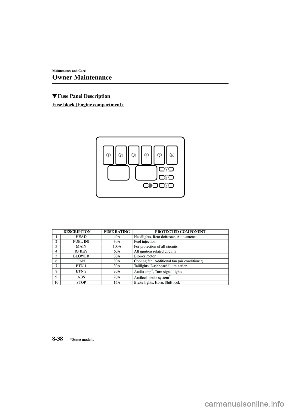
�Fuse Panel Description
Fuse block (Engine compartment)
DESCRIPTION FUSE RATING
PROTECTED COMPONENT
1 HEAD 40A Headlights, Rear defroster, Auto antenna
2 FUEL INJ 30A Fuel injection
3 MAIN 100A For protection of all circuits
4 IG KEY 60A All ignition related circuits
5 BLOWER 30A Blower motor
6 FAN 30A Cooling fan, Additional fan (air conditioner)
7 BTN 1 30A Taillights, Dashboard illumination
8BTN 2 20A Audio amp
*, Turn signal lights
9 ABS 20A Antilock brake system*
10 STOP15A Brake lights, Horn, Shift lock
*Some models.
J07S_8S15-EA-03G_Edition2.book Page 38 Thursday, August 21, 2003 10:04 AM
Page 274 of 280

10-6
Specifications
Form No. 8S15-EA-03G
�Light Bulbs
Exterior light
Interior light
�Tires
Check the tire pressure label for tire size and inflation pressure. Refer to Tire Inflation
Pressure on page 8-28
Standard tire
Temporary spare tire
�Fuses
Refer to the fuse rating on page 8-36
Light bulb
WattageCategory
ECE R SAE
Headlights High beam
60HB3 —
Low beam 51HB4 —
Front turn signal lights/Parking lights 27/8—#1157NA
Fog lights
*55 H11 —
Side-marker lights 3.8—#194
Rear turn signal lights 21 WY21W—
Brake lights/Taillights 21/5 W21/5W #7443
High-mount brake light 21 P21W—
Reverse lights 21 W21W #7440
License plate lights/Trunk lights 5W5W —
Light bulb Wattage
Overhead light 8
NOTE
The tires have been optimally matched with the chassis of your vehicle.
When replacing tires, Mazda recommends that you replace tires of the same type
originally fitted to your vehicle. For details, contact an Authorized Mazda Dealer.
Tire sizeInflation pressure
Front Rear
195/50 R15 82V 180 kPa (1.8 kgf/cm
2, 26 psi)180 kPa (1.8 kgf/cm2, 26 psi)
205/45 R16 83W
Tire size Inflation pressure
T115/70 D14 88M 420 kPa (4.2 kgf/cm
2, 60 psi)
T105/70 D15 85M 420 kPa (4.2 kgf/cm2, 60 psi)
*Some models.
J07S_8S15-EA-03G_Edition2.book Page 6 Thursday, August 21, 2003 10:04 AM