Page 202 of 304
Exceeding any vehicle weight rating limitation could result in
serious damage to the vehicle and/or personal injury.
TRAILER TOWING
Your vehicle is classified as a light duty towing vehicle. Do not tow a
trailer until your vehicle has been driven at least 2,000 miles (3,200 km).
Towing a trailer places an additional load on your vehicle’s engine,
transmission, brakes, tires and suspension. Inspect these components
carefully after towing.
Your loaded trailer should weigh no more than 2,000 lbs. (907 kg).Do
not exceed the GVWR specified on the certification label.
Towing trailers beyond the maximum recommended gross trailer
weight exceeds the limit of the vehicle and could result in
engine damage, transmission damage, structural damage, loss of vehicle
control, vehicle rollover and personal injury.
The GCW of your vehicle and trailer should not exceed 6,600 lbs. (2,993 kg).
Preparing to tow
Use the proper equipment for towing a trailer and make sure it is
properly attached to your vehicle. See your dealer or a reliable trailer
dealer if you require assistance.
Hitches
Do not use hitches that clamp onto the vehicle bumper. Use a load
carrying hitch. You must distribute the load in your trailer so that
10–15% of the total weight of the trailer is on the tongue.
Safety chains
Always connect the trailer’s safety chains to the frame or hook retainers
of the vehicle hitch. To connect the trailer’s safety chains, cross the
chains under the trailer tongue and allow slack for turning corners.
If you use a rental trailer, follow the instructions that the rental agency
gives to you.
Do not attach safety chains to the bumper.
Trailer brakes
Electric brakes and manual, automatic or surge-type trailer brakes are safe
if installed properly and adjusted to the manufacturer’s specifications. The
trailer brakes must meet local and Federal regulations.
REVIEW COPY
2004 Town Car(tow), Owners Guide (post-2002-fmt)(own2002),
Market:USA_English(fus)
Driving
202
Page 203 of 304
Do not connect a trailer’s hydraulic brake system directly to your
vehicle’s brake system. Your vehicle may not have enough
braking power and your chances of having a collision greatly increase.
The braking system of the tow vehicle is rated for operation at the
GVWR not GCWR.
Trailer lamps
Trailer lamps are required on most towed vehicles. Make sure all running
lights, brake lights, turn signals and hazard lights are working. See your
dealer or trailer rental agency for proper instructions and equipment for
hooking up trailer lamps.
Driving while you tow
When towing a trailer:
•Turn off the speed control. The speed control may shut off
automatically when you are towing on long, steep grades.
•Consult your local motor vehicle speed regulations for towing a trailer.
•To eliminate excessive shifting, use a lower gear. This will also assist
in transmission cooling. (For additional information, refer to the
Understanding the positions of the 4–speed automatic
transmissionsection in this chapter.
•Anticipate stops and brake gradually.
•Do not exceed the GCWR rating or transmission damage may occur.
Servicing after towing
If you tow a trailer for long distances, your vehicle will require more
frequent service intervals. Refer to yourScheduled Maintenance Guide
for more information.
Trailer towing tips
•Practice turning, stopping and backing up before starting on a trip to
get the feel of the vehicle trailer combination. When turning, make
wider turns so the trailer wheels will clear curbs and other obstacles.
•Allow more distance for stopping with a trailer attached.
•If you are driving down a long or steep hill, shift to a lower gear. Do
not apply the brakes continuously, as they may overheat and become
less effective.
REVIEW COPY
2004 Town Car(tow), Owners Guide (post-2002-fmt)(own2002),
Market:USA_English(fus)
Driving
203
Page 210 of 304
The fuses are coded as follows.
Fuse/Relay
LocationFuse Amp
RatingPassenger Compartment Fuse
Panel Description
1 10A Lighting Control Module (LCM),
Left-hand low beam headlamp
2 5A Back-up aide
15A Back-up aide, Fog lamps
3 10A LCM, Right-hand low beam
headlamp
4 7.5A Instrument cluster
5 7.5A LCM, Instrument panel light
6 15A EATC, Heated seats
7 15A LCM, Autolamps/PAT/Sunload
sensors, Park/Tail lamps,
Cornering lamps
8 10A Shift lock, Speed control, Air
suspension
9 20A Hi beam headlamps (LCM)
27 25
26 2423 21
2219
20
18 16
17 1514 12
1310
33
31
2932
30
28 11
97
8653
41
2RELAY
1
REVIEW COPY
2004 Town Car(tow), Owners Guide (post-2002-fmt)(own2002),
Market:USA_English(fus)
Roadside Emergencies
210
Page 211 of 304
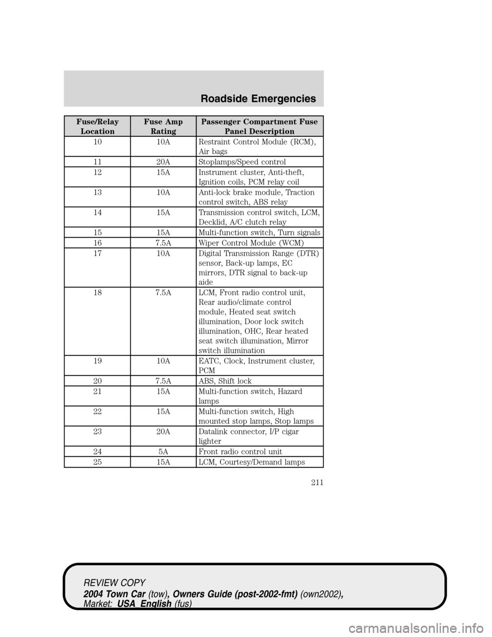
Fuse/Relay
LocationFuse Amp
RatingPassenger Compartment Fuse
Panel Description
10 10A Restraint Control Module (RCM),
Air bags
11 20A Stoplamps/Speed control
12 15A Instrument cluster, Anti-theft,
Ignition coils, PCM relay coil
13 10A Anti-lock brake module, Traction
control switch, ABS relay
14 15A Transmission control switch, LCM,
Decklid, A/C clutch relay
15 15A Multi-function switch, Turn signals
16 7.5A Wiper Control Module (WCM)
17 10A Digital Transmission Range (DTR)
sensor, Back-up lamps, EC
mirrors, DTR signal to back-up
aide
18 7.5A LCM, Front radio control unit,
Rear audio/climate control
module, Heated seat switch
illumination, Door lock switch
illumination, OHC, Rear heated
seat switch illumination, Mirror
switch illumination
19 10A EATC, Clock, Instrument cluster,
PCM
20 7.5A ABS, Shift lock
21 15A Multi-function switch, Hazard
lamps
22 15A Multi-function switch, High
mounted stop lamps, Stop lamps
23 20A Datalink connector, I/P cigar
lighter
24 5A Front radio control unit
25 15A LCM, Courtesy/Demand lamps
REVIEW COPY
2004 Town Car(tow), Owners Guide (post-2002-fmt)(own2002),
Market:USA_English(fus)
Roadside Emergencies
211
Page 212 of 304
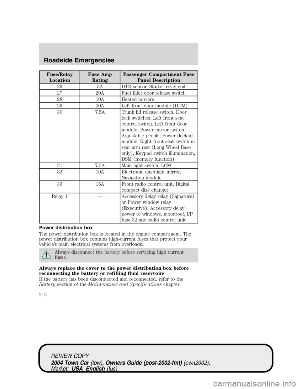
Fuse/Relay
LocationFuse Amp
RatingPassenger Compartment Fuse
Panel Description
26 5A DTR sensor, Starter relay coil
27 20A Fuel filler door release switch
28 10A Heated mirrors
29 20A Left front door module (DDM)
30 7.5A Trunk lid release switch, Door
lock switches, Left front seat
control switch, Left front door
module, Power mirror switch,
Adjustable pedals, Power decklid
module, Right front seat switch in
rear arm rest (Long Wheel Base
only), Keypad switch illumination,
DSM (memory function)
31 7.5A Main light switch, LCM
32 10A Electronic day/night mirror,
Navigation module
33 15A Front radio control unit, Digital
compact disc changer
Relay 1—Accessory delay relay (Signature)
or Power window relay
(Executive), Accessory delay
power to windows, moonroof, I/P
fuse 32 and radio control unit
Power distribution box
The power distribution box is located in the engine compartment. The
power distribution box contains high-current fuses that protect your
vehicle’s main electrical systems from overloads.
Always disconnect the battery before servicing high current
fuses.
Always replace the cover to the power distribution box before
reconnecting the battery or refilling fluid reservoirs
If the battery has been disconnected and reconnected, refer to the
Batterysection of theMaintenance and Specificationschapter.
REVIEW COPY
2004 Town Car(tow), Owners Guide (post-2002-fmt)(own2002),
Market:USA_English(fus)
Roadside Emergencies
212
Page 214 of 304
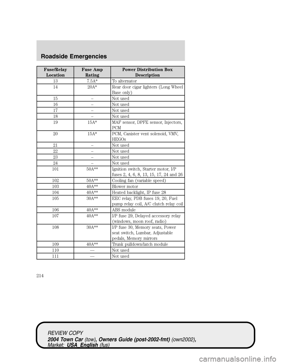
Fuse/Relay
LocationFuse Amp
RatingPower Distribution Box
Description
13 7.5A* To alternator
14 20A* Rear door cigar lighters (Long Wheel
Base only)
15–Not used
16–Not used
17–Not used
18–Not used
19 15A* MAF sensor, DPFE sensor, Injectors,
PCM
20 15A* PCM, Canister vent solenoid, VMV,
HEGOs
21–Not used
22–Not used
23–Not used
24–Not used
101 50A** Ignition switch, Starter motor, I/P
fuses 2, 4, 6, 8, 13, 15, 17, 24 and 26
102 50A** Cooling fan (variable speed)
103 40A** Blower motor
104 40A** Heated backlight, IP fuse 28
105 30A** EEC relay, PDB fuses 19, 20, Fuel
pump relay coil, A/C clutch relay coil
106 40A** ABS module
107 40A** I/P fuse 29, Delayed accessory relay
(windows, moon roof, radio)
108 30A** I/P fuse 30, Memory seats, Power
seat switch, Lumbar, Adjustable
pedals, Memory mirrors
109 40A** Trunk pulldown/latch module
110—Not used
111—Not used
REVIEW COPY
2004 Town Car(tow), Owners Guide (post-2002-fmt)(own2002),
Market:USA_English(fus)
Roadside Emergencies
214
Page 215 of 304
Fuse/Relay
LocationFuse Amp
RatingPower Distribution Box
Description
112 40A** Ignition switch, I/P fuses, 10, 12, 14,
16, 18
113 40A** I/P fuses, 1, 3, 5, 7, 9, 31
114 30A** RASM compressor
115 40A** I/P fuses 11, 19, 21, 23, 25, 27
116 30A** Wipers
117 30A** Rear power seats (Long Wheel Base
only)
118 20A** ABS
201 1/2 ISO Horn
202 1/2 ISO PCM
203 1/2 ISO Fuel pump
204 1/2 ISO A/C clutch
205—Not used
206 1/2 ISO Cornering lamp ground
207 1/2 ISO Fog lamps
208 1/2 ISO Park lamp isolation
209 1/2 ISO ABS relay
301 Full ISO Blower motor
302 Full ISO Starter solenoid
303 Full ISO Heated backlight
304 Full ISO RASM
401—Not used
501 Diode PCM
502 Diode A/C clutch
503—Not used
601—Not used
602—Not used
* Mini Fuses ** Maxi Fuses
REVIEW COPY
2004 Town Car(tow), Owners Guide (post-2002-fmt)(own2002),
Market:USA_English(fus)
Roadside Emergencies
215
Page 223 of 304
3. Park the booster vehicle close to the hood of the disabled vehicle
making sure the two vehiclesdo nottouch. Set the parking brake on
both vehicles and stay clear of the engine cooling fan and other moving
parts.
4. Check all battery terminals and remove any excessive corrosion before
you attach the battery cables. Ensure that vent caps are tight and level.
5. Turn the heater fan on in both vehicles to protect any electrical
surges. Turn all other accessories off.
Connecting the jumper cables
1. Connect the positive (+) jumper cable to the positive (+) terminal of
the discharged battery.
Note:In the illustrations,lightning boltsare used to designate the
assisting (boosting) battery.
2. Connect the other end of the positive (+) cable to the positive (+)
terminal of the assisting battery.
+–+–
+–+–
REVIEW COPY
2004 Town Car(tow), Owners Guide (post-2002-fmt)(own2002),
Market:USA_English(fus)
Roadside Emergencies
223