2004 LINCOLN TOWN CAR wheel
[x] Cancel search: wheelPage 201 of 304

GCW (Gross Combined Weight)–is the weight of the loaded vehicle
(GVW) plus the weight of the fully loaded trailer.
GCWR (Gross Combined Weight Rating)–is the maximum allowable
weight of the vehicle and the loaded trailer–including all cargo and
passengers–that the vehicle can handle without risking damage.
(Important: The towing vehicle’s braking system is rated for operation at
GVWR, not at GCWR. Separate functional brakes should be used for safe
control of towed vehicles and for trailers where the GCW of the towing
vehicle plus the trailer exceed the GVWR of the towing vehicle.The
GCW must never exceed the GCWR.
Maximum Loaded Trailer Weight–is the highest possible weight of a
fully loaded trailer the vehicle can tow. It assumes a vehicle with only
mandatory options, no cargo (internal or external), a tongue load of
10–15% (conventional trailer) or king pin weight of 15–25% (fifth wheel
trailer), and driver only (150 lbs [68 kg]).Consult your dealership (or
theRV and Trailer Towing Guideprovided by your dealership) for
more detailed information.
Tongue Load or Fifth Wheel King Pin Weight–refers to the amount
of the weight that a trailer pushes down on a trailer hitch.
Examples:For a 5,000 lbs. (2,268 kg) conventional trailer, multiply
5,000 by 0.10 and 0.15 to obtain a proper tongue load range of 500 to
750 lbs. (227 to 340 kg). For an 11,500 lbs. (5,216 kg) fifth wheel trailer,
multiply by 0.15 and 0.25 to obtain a proper king pin load range of 1,725
to 2,875 lbs. (782 to 1,304 kg)
Do not exceed the GVWR or the GAWR specified on the
certification label.
Do not use replacement tires with lower load carrying capacities
than the originals because they may lower the vehicle’s GVWR
and GAWR limitations. Replacement tires with a higher limit than the
originals do not increase the GVWR and GAWR limitations.
REVIEW COPY
2004 Town Car(tow), Owners Guide (post-2002-fmt)(own2002),
Market:USA_English(fus)
Driving
201
Page 203 of 304
Do not connect a trailer’s hydraulic brake system directly to your
vehicle’s brake system. Your vehicle may not have enough
braking power and your chances of having a collision greatly increase.
The braking system of the tow vehicle is rated for operation at the
GVWR not GCWR.
Trailer lamps
Trailer lamps are required on most towed vehicles. Make sure all running
lights, brake lights, turn signals and hazard lights are working. See your
dealer or trailer rental agency for proper instructions and equipment for
hooking up trailer lamps.
Driving while you tow
When towing a trailer:
•Turn off the speed control. The speed control may shut off
automatically when you are towing on long, steep grades.
•Consult your local motor vehicle speed regulations for towing a trailer.
•To eliminate excessive shifting, use a lower gear. This will also assist
in transmission cooling. (For additional information, refer to the
Understanding the positions of the 4–speed automatic
transmissionsection in this chapter.
•Anticipate stops and brake gradually.
•Do not exceed the GCWR rating or transmission damage may occur.
Servicing after towing
If you tow a trailer for long distances, your vehicle will require more
frequent service intervals. Refer to yourScheduled Maintenance Guide
for more information.
Trailer towing tips
•Practice turning, stopping and backing up before starting on a trip to
get the feel of the vehicle trailer combination. When turning, make
wider turns so the trailer wheels will clear curbs and other obstacles.
•Allow more distance for stopping with a trailer attached.
•If you are driving down a long or steep hill, shift to a lower gear. Do
not apply the brakes continuously, as they may overheat and become
less effective.
REVIEW COPY
2004 Town Car(tow), Owners Guide (post-2002-fmt)(own2002),
Market:USA_English(fus)
Driving
203
Page 204 of 304
•The trailer tongue weight should be 10–15% of the loaded trailer
weight.
•After you have traveled 50 miles (80 km), thoroughly check your
hitch, electrical connections and trailer wheel lug nuts.
•To aid in engine/transmission cooling and A/C efficiency during hot
weather while stopped in traffic, place the gearshift lever in P (Park).
•Vehicles with trailers should not be parked on a grade. If you must
park on a grade, place wheel chocks under the trailer’s wheels.
Launching or retrieving a boat
Disconnect the wiring to the trailer before backing the trailer
into the water. Reconnect the wiring to the trailer after the
trailer is removed from the water.
When backing down a ramp during boat launching or retrieval:
•do not allow the static water level to rise above the bottom edge of
the rear bumper.
•do not allow waves to break higher than 6 inches (15 cm) above the
bottom edge of the rear bumper.
Exceeding these limits may allow water to enter vehicle components:
•causing internal damage to the components.
•affecting driveability, emissions and reliability.
Replace the rear axle lubricant any time the axle has been submerged in
water. Rear axle lubricant quantities are not to be checked or changed
unless a leak is suspected or repair required.
RECREATIONAL TOWING (ALL WHEELS ON THE GROUND)
Follow these guidelines for your specific powertrain combination to tow
your vehicle with all four wheels on the ground (such as behind a
recreational vehicle).
These guidelines are designed to ensure that your transmission is not
damaged due to insufficient lubrication.
All Rear Wheel Drive (RWD) vehicles:
This applies to all cars and 4x2 trucks/sport utilities with rear wheel
drive capability.
•Place the transmission in N (Neutral)
•Maximum speed is 35 mph (56 km/h)
REVIEW COPY
2004 Town Car(tow), Owners Guide (post-2002-fmt)(own2002),
Market:USA_English(fus)
Driving
204
Page 207 of 304
Canadian customers who require roadside assistance, call
1–800–665–2006.
If you need to arrange roadside assistance for yourself, Ford Motor
Company will reimburse a reasonable amount. To obtain reimbursement
information, U.S. Ford or Mercury vehicles customers call
1-800-241-3673; Lincoln vehicle customers call 1–800–521–4140.
Canadian customers who need to obtain reimbursement information, call
1–800–665–2006.
ROADSIDE COVERAGE BEYOND BASIC WARRANTY
In the United States, you may purchase additional roadside assistance
coverage beyond this period through the Ford Auto Club by contacting
your Ford or Lincoln Mercury dealer.
Similarly in Canada, for uninterrupted Roadside Assistance coverage, you
may purchase extended coverage prior to your Basic Warranty’s Roadside
Assistance expiring. For more information and enrollment, contact
1–877–294–2582 or visit our website at www.ford.ca.
HAZARD FLASHER
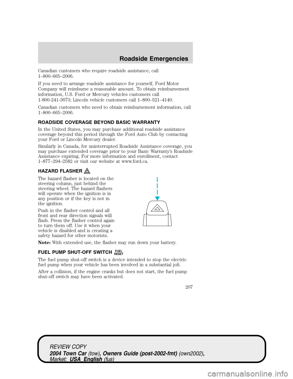
The hazard flasher is located on the
steering column, just behind the
steering wheel. The hazard flashers
will operate when the ignition is in
any position or if the key is not in
the ignition.
Push in the flasher control and all
front and rear direction signals will
flash. Press the flasher control again
to turn them off. Use it when your
vehicle is disabled and is creating a
safety hazard for other motorists.
Note:With extended use, the flasher may run down your battery.
FUEL PUMP SHUT-OFF SWITCH
FUEL
RESET
The fuel pump shut-off switch is a device intended to stop the electric
fuel pump when your vehicle has been involved in a substantial jolt.
After a collision, if the engine cranks but does not start, the fuel pump
shut-off switch may have been activated.
REVIEW COPY
2004 Town Car(tow), Owners Guide (post-2002-fmt)(own2002),
Market:USA_English(fus)
Roadside Emergencies
207
Page 209 of 304

Standard fuse amperage rating and color
COLOR
Fuse
ratingMini
fusesStandard
fusesMaxi
fusesCartridge
maxi
fusesFuse link
cartridge
2A Grey Grey———
3A Violet Violet———
4A Pink Pink———
5A Tan Tan———
7.5A Brown Brown———
10A Red Red———
15A Blue Blue———
20A Yellow Yellow Yellow Blue Blue
25A Natural Natural———
30A Green Green Green Pink Pink
40A——Orange Green Green
50A——Red Red Red
60A——Blue—Yellow
70A——Ta n—Brown
80A——Natural—Black
Passenger compartment fuse panel
The fuse panel is located below and to the left of the steering wheel by
the brake pedal. Remove the panel cover to access the fuses.
To remove a fuse use the fuse puller tool provided on the fuse panel
cover.
REVIEW COPY
2004 Town Car(tow), Owners Guide (post-2002-fmt)(own2002),
Market:USA_English(fus)
Roadside Emergencies
209
Page 212 of 304
Fuse/Relay
LocationFuse Amp
RatingPassenger Compartment Fuse
Panel Description
26 5A DTR sensor, Starter relay coil
27 20A Fuel filler door release switch
28 10A Heated mirrors
29 20A Left front door module (DDM)
30 7.5A Trunk lid release switch, Door
lock switches, Left front seat
control switch, Left front door
module, Power mirror switch,
Adjustable pedals, Power decklid
module, Right front seat switch in
rear arm rest (Long Wheel Base
only), Keypad switch illumination,
DSM (memory function)
31 7.5A Main light switch, LCM
32 10A Electronic day/night mirror,
Navigation module
33 15A Front radio control unit, Digital
compact disc changer
Relay 1—Accessory delay relay (Signature)
or Power window relay
(Executive), Accessory delay
power to windows, moonroof, I/P
fuse 32 and radio control unit
Power distribution box
The power distribution box is located in the engine compartment. The
power distribution box contains high-current fuses that protect your
vehicle’s main electrical systems from overloads.
Always disconnect the battery before servicing high current
fuses.
Always replace the cover to the power distribution box before
reconnecting the battery or refilling fluid reservoirs
If the battery has been disconnected and reconnected, refer to the
Batterysection of theMaintenance and Specificationschapter.
REVIEW COPY
2004 Town Car(tow), Owners Guide (post-2002-fmt)(own2002),
Market:USA_English(fus)
Roadside Emergencies
212
Page 213 of 304

The high-current fuses are coded as follows.
Fuse/Relay
LocationFuse Amp
RatingPower Distribution Box
Description
1 30A* Radio, I/P Fuse 33
2 20A* Front power point
3—Not used
4 15A* Horn
5 20A* Fuel pump, Inertia switch
6 20A* Right rear power point (Long Wheel
Base only)
7 30A* Front driver and front passenger
heated seats
8—Not used
9—Not used
10 10A* Rear Air Suspension Module (RASM)
11 30A* Rear driver/passenger heated seats
(Long Wheel Base only)
12 20A* Left rear power point (Long Wheel
Base only)
REVIEW COPY
2004 Town Car(tow), Owners Guide (post-2002-fmt)(own2002),
Market:USA_English(fus)
Roadside Emergencies
213
Page 214 of 304
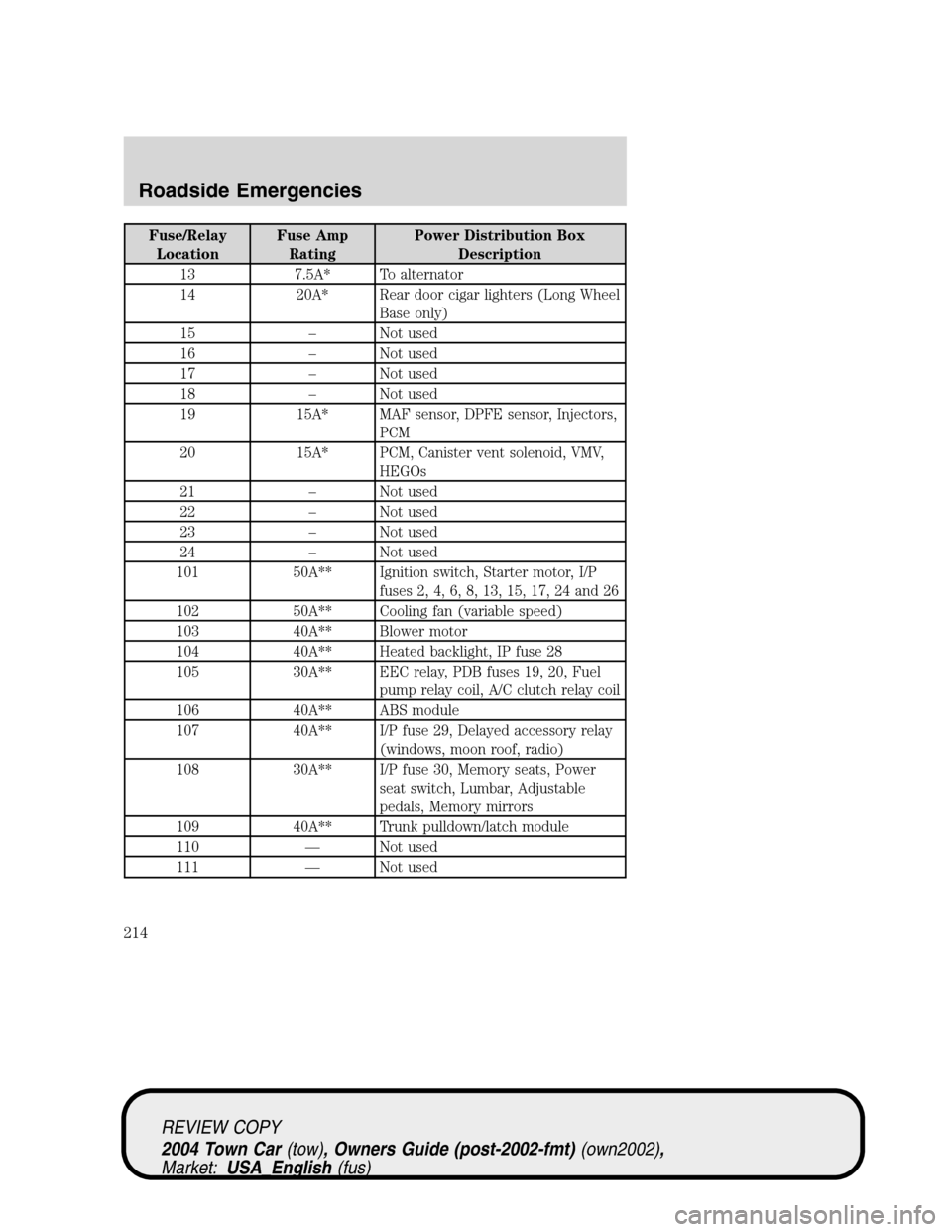
Fuse/Relay
LocationFuse Amp
RatingPower Distribution Box
Description
13 7.5A* To alternator
14 20A* Rear door cigar lighters (Long Wheel
Base only)
15–Not used
16–Not used
17–Not used
18–Not used
19 15A* MAF sensor, DPFE sensor, Injectors,
PCM
20 15A* PCM, Canister vent solenoid, VMV,
HEGOs
21–Not used
22–Not used
23–Not used
24–Not used
101 50A** Ignition switch, Starter motor, I/P
fuses 2, 4, 6, 8, 13, 15, 17, 24 and 26
102 50A** Cooling fan (variable speed)
103 40A** Blower motor
104 40A** Heated backlight, IP fuse 28
105 30A** EEC relay, PDB fuses 19, 20, Fuel
pump relay coil, A/C clutch relay coil
106 40A** ABS module
107 40A** I/P fuse 29, Delayed accessory relay
(windows, moon roof, radio)
108 30A** I/P fuse 30, Memory seats, Power
seat switch, Lumbar, Adjustable
pedals, Memory mirrors
109 40A** Trunk pulldown/latch module
110—Not used
111—Not used
REVIEW COPY
2004 Town Car(tow), Owners Guide (post-2002-fmt)(own2002),
Market:USA_English(fus)
Roadside Emergencies
214