Page 8 of 315
Your vehicle at a glance
2
2
1 23456789
EXTERIOR OVERVIEW
1. Headlights
2. Turn signal light
3. Engine hood
4. Wiper
5. Sunroof (if equipped)
6. Window
7. Outside rearview mirror
8. Door
1LDN0001
Page 11 of 315
25
1 23456789
Your vehicle at a glance
INSTRUMENT PANEL OVERVIEW
1. Driver’s Air Bag (if equipped)
2. Light control / Turn signals
3. Instrument cluster
4. Wiper/Washer
5. Ignition switch
6. Seat warmer(if equipped)
7. Traction control system (if equipped)
8. Hazard
9. Climate control system
10. Shift lever
11. Passenger’s airbag (if equipped)
12. Glove box
13. Audio controls (if equipped)
14. Auto cruise controls (if equipped)
1LDE0003
Page 18 of 315

37
1 23456789
Knowing your vehicle
Your vehicle is equipped with an
electronic engine immobilizer system
to reduce the risk of unauthorized
vehicle use.
Your immobilizer system is com-
prised of a small transponder in the
ignition key, and antenna coil in the
key cylinder and BCM (Body Control
Module) in the instrument panel.
With this system, whenever you
insert your ignition key into the igni-
tion switch and turn it to ON, the
antenna coil in the ignition switch
receives a signal from the transpon-
der in the ignition key and then sendsthe signal to the BCM (Body controlModule).
The BCM checks the signal whether
the ignition key is valid.
If the key is determined to be valid,
the engine will start.
If the key is determined to be invalid,
the engine will not start.To deactivate the immobilizer sys-tem:
Insert the ignition key into the key
cylinder and turn it to the ON posi-tion.
To activate the immobilizer sys- tem:
Turn the ignition key to the OFF posi-
tion. The immobilizer system acti-
vates automatically. Without a valid
ignition key for your vehicle, the
engine will not start.
IMMOBILIZER SYSTEM (IF EQUIPPED)CAUTION
The transponder in your ignition
key is an important part of theimmobilizer system. It is designed to give years of trou-blefree service, however youshould avoid exposure to mois- ture, static electricity and roughhandling. Immobilizer systemmalfunction could occur.
CAUTION
Do not change, alter or adjustthe immobilizer system becauseit could cause the immobilizer system to malfunction andshould only be serviced by anauthorized Kia dealer. Malfunctions caused by improp-er alterations, adjustments ormodifications to the immobilizer system are not covered by yourvehicle manufacturer warranty.
Page 80 of 315

369
1 23456789
Knowing your vehicle
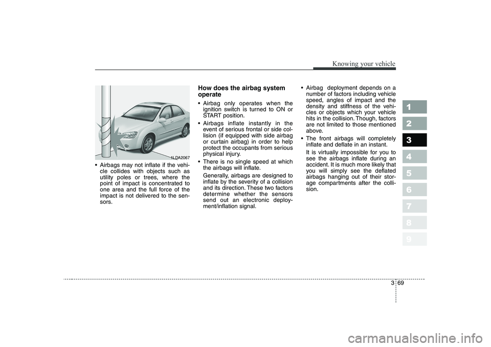
Airbags may not inflate if the vehi-cle collides with objects such as
utility poles or trees, where the
point of impact is concentrated to
one area and the full force of the
impact is not delivered to the sen-
sors. How does the airbag system operate
Airbag only operates when the
ignition switch is turned to ON or
START position.
Airbags inflate instantly in the event of serious frontal or side col-lision (if equipped with side airbag
or curtain airbag) in order to help
protect the occupants from serious
physical injury.
There is no single speed at which the airbags will inflate.
Generally, airbags are designed to
inflate by the severity of a collision
and its direction. These two factors
determine whether the sensors
send out an electronic deploy-ment/inflation signal. Airbag deployment depends on a
number of factors including vehiclespeed, angles of impact and the
density and stiffness of the vehi-
cles or objects which your vehicle
hits in the collision. Though, factorsare not limited to those mentioned
above.
The front airbags will completely inflate and deflate in an instant.
It is virtually impossible for you to
see the airbags inflate during an
accident. It is much more likely that
you will simply see the deflatedairbags hanging out of their stor-
age compartments after the colli-sion.
1LDA2067
Page 111 of 315
Knowing your vehicle
100
3
1 23456789
Fixed rod antenna (if equipped)
Your car uses a fixed rod antenna to
receive both AM and FM broadcast
signals.
This antenna is removable. To
remove the antenna, turn it counter-
clockwise. To install the antenna, turn
it clockwise. Roof type antenna (if equipped)
If your vehicle has an audio system, an amplifying antenna is installed in
your vehicle. This antenna can be adjusted up and
down or removed from the vehicle
when you wash your vehicle.
✽✽
NOTICE
Page 112 of 315
3 101
1 23456789
Knowing your vehicle
Manual antenna (if equipped)
Your car uses a manual stainless
steel antenna to receive both AM
and FM broadcast signals. Pull up
the antenna using your fingers, as
shown in the drawing.
✽✽NOTICE
Before entering an automatic car
wash or a place with a low height
clearance, be sure that the antenna
is fully retracted.
Power antenna (if equipped) The antenna will automatically be
extended when the radio power
switch is turned “ON” while the igni-
tion key is either in the “ON” or “ACC”
position. The antenna will automati-
cally be retracted and stored when
either the radio power switch is
turned “OFF” or the ignition key is set
to the “LOCK” position.
✽✽ NOTICE
Page 145 of 315
433
1 23456789
Driving your vehicle
INSTRUMENT CLUSTER
1. Tachometer
2. Turn signal indicators
3. Speedometer4. Engine temperature gauge
5. Warning and indicator lights
6. Odometer / Tripmeter
7. Tripmeter mode/reset button8. Shift position indicator
(Automatic transaxle only)
9. Fuel gauge
10. Trip computer (if equipped)
1LDE2090/1LDE2090A/1LDE2090B/1LDE2090C
■■ Gasoline (Type A)
■
■ Gasoline (Type B) ■
■
Diesel (Type A)
■
■ Diesel (Type B)
➀➁➁
➂
➃
➄➄➅
➉➇
➆
➈
➀➁➁
➂
➃
➄➄➅
➉➇
➆
➈
➀➁➁
➂
➃
➄➄➅
➉➇
➆
➈
➀➁➁
➂
➃
➄➄➅
➉➇
➆
➈
Page 160 of 315
Driving your vehicle
48
4
1 23456789
High - beam operation
To turn on the high beam headlights,
push the lever away from you. Pull it
back for low beams. The high-beam indicator will light when the headlight high beams are
switched on.
To prevent the battery from being
discharged, do not leave the lights
on for a prolonged time while the
engine is not running.Flashing headlights
To flash the headlights, pull the lever
towards you. It will return to the nor-
mal (low-beam) position when
released. The headlight switch doesnot need to be on to use this flashing
feature.
Turn signals ( )
The ignition switch must be on for the
turn signals to function. To turn on
the turn signals, move the lever up or
down. Green arrow indicators on the
instrument panel indicate which turn
signal is operating. They will self-
cancel after a turn is completed. If
the indicator continues to flash after
a turn, manually return the lever tothe OFF position.
1LDA21051LDN21071LDA2106
A