Page 2536 of 4264
6C-12 ENGINE FUEL (C24SE)
Fuel Pump Relay
General Description
In order to control the fuel pump and sender assembly
(FPAS) operation, the FPAS relay is provided. When
the starter switch is turned to “ON" position, the FPAS
relay operates the FPAS for 2 seconds.
When it is turned to “START" position, the Engine
Control Module receives the reference pulse from the
Ignition Control Module and it operates the relay, again
causing the FPAS to feed fuel.
Page 2547 of 4264

ENGINE ELECTRICAL 6D1-5
Battery fluid is a highly corrosive acid.
Should battery fluid come in contact with your eyes, skin,
fabric, or a painted surface, immediately and thoroughly rinse
the affected area with clean tap water.
Never allow metal tools or jumper cables to come in contact
with the positive battery terminal, or any other metal surface of
the vahicle. This will protect against a short circuit.
Always keep batteries out of reach of young children.
Jump Starting Procedure
1. Set the vehicle parking brake.
If the vahicle is equipped with an automatic transmission,
place the selector level in the "PARK" position.
If the vehicle is equipped with a manual transmission, place
the shift lever in the "NEUTRAL" position.
Turn "OFF" the ignition.
Turn "OFF" all lights and any other accessory requiring
electrical power.
2. Look at the built-in hydrometer.
If the indication area of the built-in hydrometer is completely
clear, do not try to jump start.
3.
Attach the end of one jumper cable to the positive terminal
of the booster battery.
Attach the other end of the same cable to the positive
terminal of the discharged battery.
Do not allow the vehicles to touch each other. This will
cause a ground connection, effectively neutralizing the
charging procedure.
Be sure that the booster battery has a 12 volt rating.
4.
Attach one end of the remaining cable to the negative
terminal of the booster battery.
Attach the other end of the same cable to a solid engine
ground (such as the air conditioning compressor bracket o
r
the generator mounting bracket) of the vehicle with the
discharged battery.
The ground connection must be at least 450 mm (18 in.)
from the battery of the vehicle whose battery is being
charged.
WARNING: NEVER ATTACH THE END OF THE JUMPER
CABLE DIRECTLY TO THE NEGATIVE TERMINAL OF THE
DEAD BATTERY.
5. Start the engine of the vehicle with the good battery.
Make sure that all unnecessary electrical accessories have
been turned "OFF".
6. Start the engine of the vehicle with the dead battery.
7. To remove the jumper cables, follow the above directions in
reverse order.
Be sure to first disconnect the negative cable from the
vehicle with the discharged battery.
Page 2549 of 4264

IGNITION SYSTEM 6D2-1
SECTION 6D2
IGNITION SYSTEM
CONTENTS
PAGE
General Description........................................................................................................ 6D2- 2
Service Precaution ......................................................................................................... 6D2- 2
Diagnosis......................................................................................................................... 6D2- 2
Ignition Coil ..................................................................................................................... 6D2- 2
Removal ...................................................................................................................... 6D2- 2
Installation .................................................................................................................. 6D2- 2
Spark Plug ....................................................................................................................... 6D2- 3
Removal ...................................................................................................................... 6D2- 3
Inspection and Repair................................................................................................ 6D2- 3
Installation .................................................................................................................. 6D2- 4
Crankshaft Angle Sensor ............................................................................................... 6D2- 4
Removal ...................................................................................................................... 6D2- 4
Installation .................................................................................................................. 6D2- 4
Main Data and Specifications ........................................................................................ 6D2- 5
Page 2550 of 4264

6D2-2 IGNITION SYSTEM
General Description
Ignition is done by the Ignition Module that fires.
Since the cylinder on exhaust stroke requires less energy to
fire its spark plug, energy from the ignition coils can be utilized
to fire the mating cylinder on compression stroke.
A notch in the timing disc on the crankshaft activates the crank
angle sensor which then sends information such as firing order
and starting timing of ignition coil to the ECM.
By receiving signals such as crank position, engine speed,
water temperature and Manifold Absolute Pressure (MAP), the
ECM controls the ignition timing.
Service Precaution
CAUTION:
Always use the correct fastener in the proper location.
When you replace a fastener, use ONLY the exact part
number for that application. ISUZU will call out those
fasteners that require a replacement after removal. ISUZU
will also call out the fasteners that require thread lockers
or thread sealant. UNLESS OTHERWISE SPECIFIED, do
not use supplemental coatings (Paints, greases, or other
corrosion inhibitors) on threaded fasteners or fastener
joint interfaces. Generally, such coatings adversely affect
the fastener torque and the joint clamping force, and may
damage the fastener. When you install fasteners, use the
correct tightening sequence and specifications. Following
these instructions can help you avoid damage to parts
and systems.
Diagnosis
Refer to Section Drivability and Emissions for the diagnosis to
electronic ignition system (El system).
Ignition Coil
Removal
1. Disconnect battery ground cable.
2. Disconnect the Ignition coil connector.
3. Remove the ignition coil.
Installation
1. Install the ignition coil.
Connect ignition coil connector and ignition coil, then tighten
bolt to the specified torque.
Torque: 20 N�
�� �m (2.0 kgf�
�� �m)
2. Connect battery ground cable.
Page 2551 of 4264

IGNITION SYSTEM 6D2-3
Spark Plug
Removal
1. Remove spark plugs.
Inspection and Repair
The spark plug affects entire engine performance and
therefore its inspection is very important.
�
Check electrode and insulator for presence of cracks, and
replace if any.
�
Check electrode for wear, and replace if necessary.
�
Check gasket for damage, and replace if necessary.
�
Measure insulation resistance with an ohmmeter, and
replace if faulty.
� Adjust spark plug gap to 1.0 - 1.1 mm (0.027 in) - 0.8 mm
(0.031 in).
�
Check fuel and electrical systems if spark plug is extremel
y
dirty.
�
Use spark plugs having low heat value (hot type plug) if fuel
and electrical systems are normal.
�
Use spark plugs having high heat value (cold type plug) i
f
insulator and electrode are extremely burned.
Sooty Spark Plugs
Much deposit of carbon or oil on the electrode and insulator of
spark plug reduces the engine performance.
Possible causes:
� Too rich mixture
�
Presence of oil in combustion chamber
�
Incorrectly adjusted spark plug gap
Burning Electrodes
This fault is characterized by scorched or heavily oxidized
electrode or blistered insulator nose.
Possible causes:
�
Too lean mixture
�
Improper heat value
Measuring Insulation Resistance
�
Measure insulation resistance using a 500 volt megaohm
meter.
� Replace spark plugs if measured value is out of standard.
Insulation resistance: 50 M
�
�� � or more
Page 2552 of 4264
6D2-4 IGNITION SYSTEM
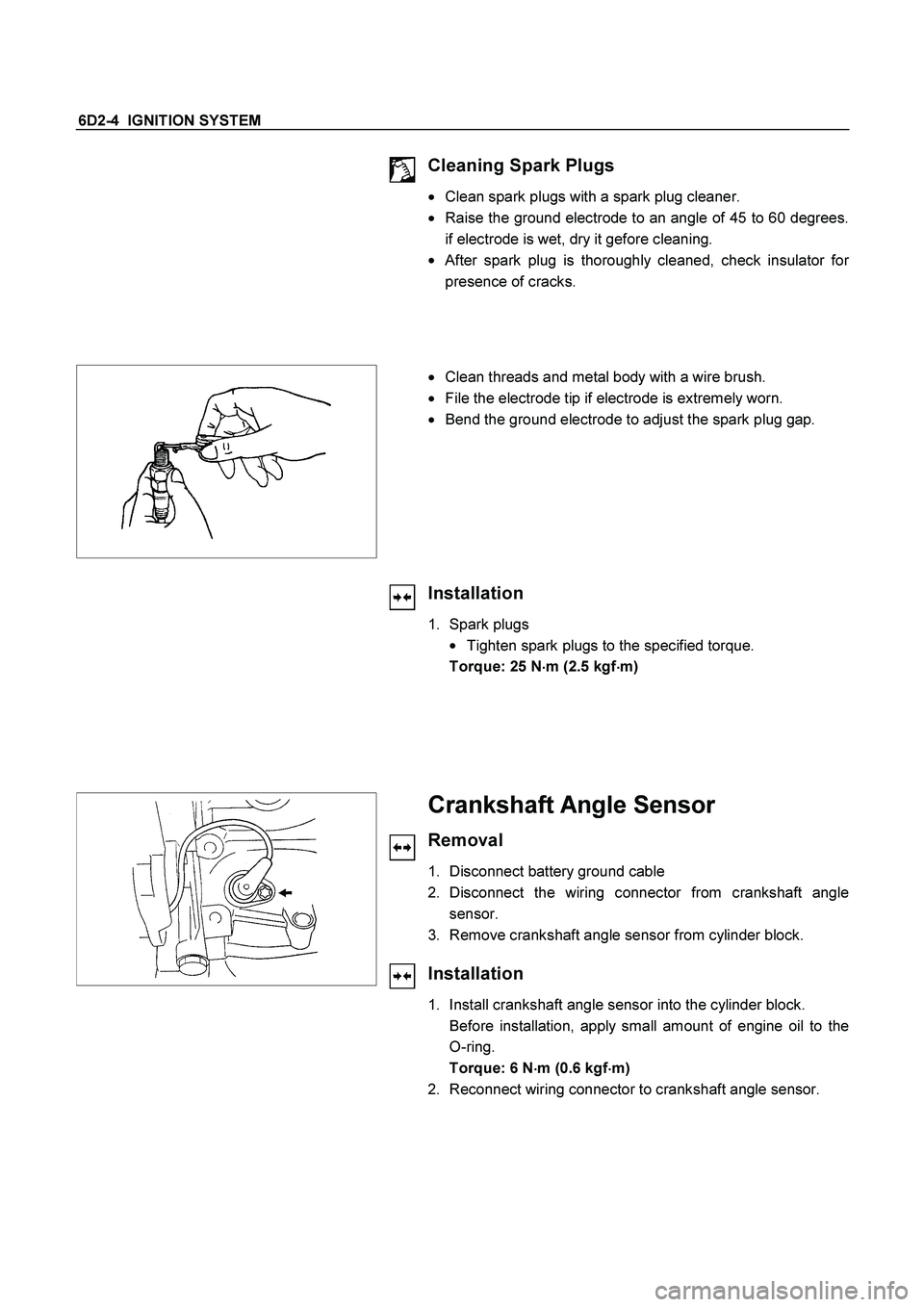
Cleaning Spark Plugs
�
Clean spark plugs with a spark plug cleaner.
� Raise the ground electrode to an angle of 45 to 60 degrees.
if electrode is wet, dry it gefore cleaning.
�
After spark plug is thoroughly cleaned, check insulator for
presence of cracks.
�
Clean threads and metal body with a wire brush.
�
File the electrode tip if electrode is extremely worn.
�
Bend the ground electrode to adjust the spark plug gap.
Installation
1. Spark plugs
�
Tighten spark plugs to the specified torque.
Torque: 25 N
�
�� �m (2.5 kgf
�
�� �m)
Crankshaft Angle Sensor
Removal
1. Disconnect battery ground cable
2. Disconnect the wiring connector from crankshaft angle
sensor.
3. Remove crankshaft angle sensor from cylinder block.
Installation
1. Install crankshaft angle sensor into the cylinder block.
Before installation, apply small amount of engine oil to the
O-ring.
Torque: 6 N
�
�� �m (0.6 kgf
�
�� �m)
2. Reconnect wiring connector to crankshaft angle sensor.
Page 2553 of 4264
IGNITION SYSTEM 6D2-5
Main Data and Specifications
General Specifications
Ignition System
Ignition Form Electronic Ignition System (El system) with Crankshaft angle Sensor
Spark Plug
Type
No. of Coils and Type
Coil Location
Torque Electronic Spark Control
2 Solid State
Engine-mounted
20 N�m (2.0 kgf�m)
Page 2554 of 4264
6D2-6 IGNITION SYSTEM
MEMO

Fuel Pump Relay
General Description
In order to control the fuel pump and sender assembly
(FPAS) operation, the FPAS relay is provided. When
the starter switch is turned")
 with Crankshaft angle Sensor
Spark Plug
Type")
