Page 3173 of 4264
MANUAL TRANSMISSION 7B1-9
6. Remove gear control lever (5).
7. Raise and support vehicle with suitable stands.
8. Remove rear propeller shaft (6).
NOTE: Apply alignment marks on the flange at the
differential side.
401RS023
9. Loosen the front exhaust pipe fixing nuts (7) at the
engine side but not remove them. (Diesel engine
only)
150R300003
10. Remove the exhaust pipe (8). (6VE1 only)
RTW37ASH0001
11. Disconnect harness connectors and clips on the
transmission.
� Neutral Switch
�
Back up Switch
� Car Speed Sensor
12. Remove the fuel pipe bracket (9) with pipes from the
transmission (17).
Diesel engine
220R300012
Legend
(1) Bolt
(2) Nut
(3) Fuel Pipe Assembly
Page 3180 of 4264
. (Diesel engine only)
NOTE: Tighten the lower bolt temporarily.
After installing the fuel pipe assembly, tighten the bolt to
the specified")
7B1-16 MANUAL TRANSMISSION
6. Install starter(15). (Diesel engine only)
NOTE: Tighten the lower bolt temporarily.
After installing the fuel pipe assembly, tighten the bolt to
the specified torque.
Torque: 76 N�
�� �m (7.7 kg�
�� �m/56 lb�
�� �ft)
7. Install the rear support rubber (14) on the
transmission and tighten the nuts to the specified
torque.
Torque: 52 N�
�� �m (5.3 kg�
�� �m/38 lb�
�� �ft)
8. Install the middle part of transmission crossmember
(12) and bolts.
Tighten the nuts to the specified torque.
Torque: 67 N�
�� �m (6.8 kg�
�� �m/49 lb�
�� �ft)
9. Install engine rear mount nuts (11) fixing on
transmission crossmember (12).
Torque: 52 N�
�� �m (5.3 kg�
�� �m/38 lb�
�� �ft)
Remove the transmission jack from transmission
side.
10. Apply grease to top hole portion of the shift fork.
Install slave cylinder (10) and tighten the bolts to the
specified torque.
Torque: 76 N�
�� �m (7.7 kg�
�� �m/56 lb�
�� �ft)
11. Install the fuel pipe brackets (9) on the transmission.
Install the fuel pipe assembly to the fuel brackets.
Torque: Bolt & Nut 76 N�
�� �m (7.7 kg�
�� �m/56 lb�
�� �ft)
Nut 37 N�
�� �
m (3.8 kg�
�� �
m/28 lb�
�� �
ft)
Diesel engine
220R300012
Legend
(1) Bolt
(2) Nut
(3) Fuel Pipe Assembly
6VE1, C24NE
Scan-1
12. Connect transmission harness connectors and clip.
Connector: neutral switch, car speed sensor, and
backup switch.
13. Tighten exhaust pipe fixing nuts (7) to the specified
torque. (Diesel engine only)
Torque: 67 N�
�� �m (6.8 kg�
�� �m/49 lb�
�� �ft)
150R300003
Page 3228 of 4264
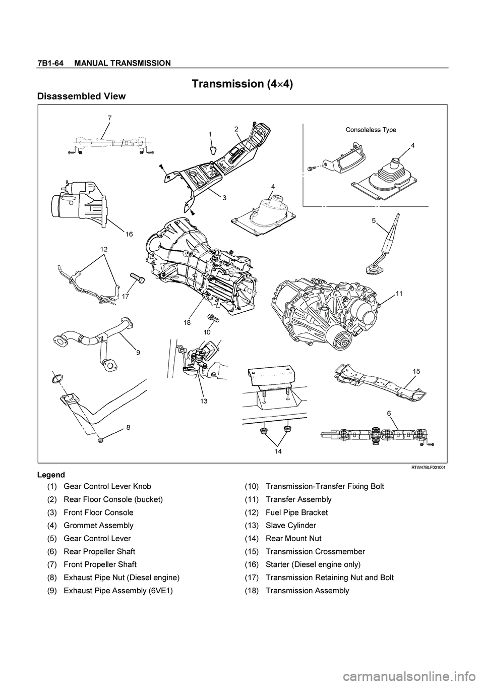
7B1-64 MANUAL TRANSMISSION
Transmission (4�
�� �
4)
Disassembled View
RTW47BLF001001
Legend
(1) Gear Control Lever Knob (10) Transmission-Transfer Fixing Bolt
(2) Rear Floor Console (bucket) (11) Transfer Assembly
(3) Front Floor Console (12) Fuel Pipe Bracket
(4) Grommet Assembly (13) Slave Cylinder
(5) Gear Control Lever (14) Rear Mount Nut
(6) Rear Propeller Shaft (15) Transmission Crossmember
(7) Front Propeller Shaft (16) Starter (Diesel engine only)
(8) Exhaust Pipe Nut (Diesel engine) (17) Transmission Retaining Nut and Bolt
(9) Exhaust Pipe Assembly (6VE1) (18) Transmission Assembly
Page 3231 of 4264
MANUAL TRANSMISSION 7B1-67
13. Remove transmission-transfer fixing bolts (10), and
remove the transfer assembly (11) from the
transmission.
14. Disconnect harness connectors and clips on the
transmission.
�
Neutral switch; Transmission
� Back up Switch
� 2W-4W Switch
�
Neutral Switch; Transfer
15. Remove the fuel pipe brackets (12) with pipes from
the transmission (18).
Diesel engine
220R300012
Legend
(1) Bolt
(2) Nut
(3) Fuel Pipe Assembly
6VE1, C24NE
Scan-2
16. Remove slave cylinder (13) and put aside it.
220LV019
17. Support transmission with a transmission jack.
220RS0001
18. Remove engine rear mount nuts (14) from
transmission crossmember (15).
Page 3237 of 4264
.(Diesel engine)
NOTE: Tighten the lower bolt temporarily.
After installing the fuel pipe assembly, tighten the bolt to
the specified torque")
MANUAL TRANSMISSION 7B1-73
6. Install starter(16).(Diesel engine)
NOTE: Tighten the lower bolt temporarily.
After installing the fuel pipe assembly, tighten the bolt to
the specified torque.
Torque: 76 N�
�� �m (7.7 kg�
�� �m/56 lb�
�� �ft)
7. Install the rear support rubber on the transmission
and tighten the bolts to the specified torque.
Torque: 50 N�
�� �m (5.1 kg�
�� �m/37 lb�
�� �ft)
8. Install the middle part of transmission crossmember
(15) and bolts.
Tighten the nuts to the specified torque.
Torque: 67 N�
�� �m (6.8 kg�
�� �m/49 lb�
�� �ft)
9. Install engine rear mount nuts (14).
Torque: 52 N�
�� �m (5.3 kg�
�� �m/38 lb�
�� �ft)
Remove the transmission jack from transmission
side.
10. Apply grease to top hole portion of the shift fork.
Install slave cylinder (13) and tighten the bolts to the
specified torque.
Torque: 76 N�
�� �m (7.7 kg�
�� �m/56 lb�
�� �ft)
11. Install the fuel pipe brackets on the transmission.
Install the fuel pipe assembly to the fuel pipe
brackets
Torque: Bolt & Nut 76 N�
�� �m (7.7 kg�
�� �m/56 lb�
�� �ft)
Nut 37 N�
�� �m (3.8 kg�
�� �m/28 lb�
�� �ft)
Diesel engine
220R300012
Legend
(1) Bolt
(2) Nut
(3) Fuel Pipe Assembly
6VE1, C24NE
Scan-2
12. Connect transmission harness connectors and clips.
Connector: transfer neutral switch, 2W - 4W switch,
backup switch, transmission neutral switch.
810R300069
Legend
(1) Neutral Switch Connector: Transmission
(2) Backup Switch Connector
(3) Speed Sensor Connector
(4) Actuator Connector
(5) 2W - 4W Switch connector
(6) Neutral Switch Connector: Transfer
13. Apply grease (BESCO L2 or equivalent) on the
splined portion of the output shaft.
14. Connect the transfer to the transmission.
Page 3289 of 4264
IMMOBILIZER SYSTEM 11A-3
General Description
The immobilizer system consists of the four major
components which are Engine Control Module (ECM),
Immobilizer Control Unit (lCU), transponder, and scan
tool (Tech-2).
This system can be activated by a correctly programmed
transponder and starter switch is set to OFF.
This system can be deactivated by a correctl
y
programmed transponder key connected with a correctly
programmed ECM and a correctly programmed lCU.
While the system is on :
The starter cut off relay deactivates function of starter,
and the fuel injector power source is deactivated also.
�
Check Engine lamp is flashing.
�
Warning buzzer is operating.
(With antitheft system)
�
�� � Gasoline Engine (6VE1, C24SE)
LTW3BALF000101
Page 3299 of 4264
IMMOBILIZER SYSTEM 11A-13
Immobilizer control unit (ICU);
Mechanical Control Engine (4JA1-T)
Immobilizer control unit (ICU) permits engine starting,
when the security code which compares the securit
y
code registered into the transponder (key) and the
security code registered into ICU, and is similarl
y
registered into ICU and engine immobilizer unit (DDS-1)
is compared and it is judged that it is normal. When the
code registered into the key is unusual, and when not
recognizing a security code, engine immobilizer unit
does not permit starting of engine by the fuel cut valve
on the fuel pump.
The engine immobilizer unit is located with fuel cut
valve on fuel pump 4JA1-T engine.
The immobilizer control unit decides whether there is an
abnormality the security code based on the engine
immobilizer unit security code.
When the problem found, the engine immobilizer unit
stops fuel fupply by the fuel cut valve.
RAW4B0SF000101
Page 3591 of 4264
TRANSFER CASE 7D-3
General Description
RUW34DLF000701
The transfer case is used to provide a means of
providing power flow to the front axle. The transfer case
also provides a means of disconnecting the front axle,
providing better fuel economy and quieter operation
when the vehicle is driven on improved roads where
four wheel drive is not required. In addition, the transfer
case provides an additional gear reduction when placed
in low range, which is useful when difficult off-road
conditions are encountered.
Use the 4WD switch on the center cluster panel to
select the drive range. The 4WD indicator lamp will be
lit when 4WD is selected.
.
7. Raise and support vehicle with suitable stands.
8. Remove rear propeller shaft (6).
NOTE: Apply alignment marks on the fla")
, and
remove the transfer assembly (11) from the
transmission.
14. Disconnect harness connectors and clips on th")
,
Immobilizer Control Unit (lCU), transponder, and s")
;
Mechanical Control Engine (4JA1-T)
Immobilizer control unit (ICU) permits engine starting,
when the security code which compares the secur")
