Page 4170 of 4264
7A3-18 ON-VEHICLE SERVICE (JR405E)
CONTROL VALVE ASSEMBLY
244L300001
Remove or Disconnect
1. Block the wheels.
2. Disconnect the negative battery cable.
3. Drain the fluid.
Refer to “ATF CHANGE” in this section.
4. Remove the 19 bolts and oil pan.
5. Inspect the bottom of the oil pan and strainer netting
for foreign material (clutch facing and metal
shavings).
If there is an excessive accumulation of foreign
material, the oil strainer must be replaced.
Further inspection is required to determine the
source of the foreign material.
6. Disconnect the 2 harness connectors leading to the
control valve.
7. Remove the 12 bolts and the control valve assembly.
Number of bolts Length
10 (A)
2 (B) 40 mm (1.57 in)
30 mm (1.18 in)
Note:
Take care not to disturb the manual valve (inside the
control valve assembly).
Do not allow the pin to fall free (the pin prevents the
valve from turning).
Page 4177 of 4264
UNIT REPAIR (JR405E) 7A4-3
Disassembly steps
1. Torque converter
� Pull the torque converter free.
NOTE:
Place a pan beneath the torque converter to catch
automatic transmission fluid (ATF) spillage.
� Draining the ATF from the torque converter.
01ASSY101
2. Turbine sensor and speed sensor
� Remove the turbine sensor from the transmission case.
02ASSY103
�
Remove the speed sensor from the transmission case.
03ASSY106
3. Inhibitor switch
Remove the 2 bolts and the inhibitor switch from the
transmission case.
240L300002
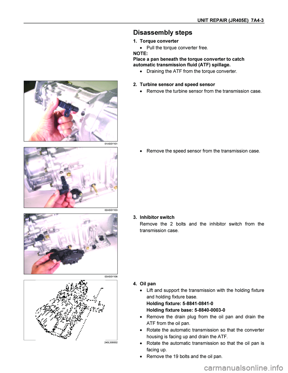
4. Oil pan
� Lift and support the transmission with the holding fixture
and holding fixture base.
Holding fixture: 5-8841-0841-0
Holding fixture base: 5-8840-0003-0
� Remove the drain plug from the oil pan and drain the
ATF from the oil pan.
� Rotate the automatic transmission so that the converte
r
housing is facing up and drain the ATF.
� Rotate the automatic transmission so that the oil pan is
facing up.
� Remove the 19 bolts and the oil pan.
Page 4257 of 4264
 7A4-83
Torque: 5.5 N�
�� �m (48 Ib�
�� �in)
� Remove the holding fixture from the transmission case.
RTW47ASH001001
23.Speed sensor and turbine sensor
� Apply ATF")
UNIT REPAIR (JR405E) 7A4-83
Torque: 5.5 N�
�� �m (48 Ib�
�� �in)
� Remove the holding fixture from the transmission case.
RTW47ASH001001
23.Speed sensor and turbine sensor
� Apply ATF to the new O-rings and install them the speed
sensor (2) and the turbine sensor (3).
� Install the speed sensor and the turbine sensor. Tighten
the bolt to the specified torque.
Torque: 6 N�
�� �m (52 Ib�
�� �in)
24.Torque converter
� Pour the new ATF into the torque converter.
� Shake the torque converter to thoroughly clean the
inside.
� Drain the ATF from the torque converter.
� Pour the new ATF into the torque converter.
NOTE:
If significant amounts of foreign material (clutch facing,
metallic fragments, etc.) are found in the automatic
transmission at time of disassembly, the existing torque
converter must be replaced with a new one.
RTW47ASH000901
� Install the torque converter.
� Measure the torque converter end play (A).
If the measured value is greater than the specified
minimum, the torque converter is correctly installed.
Torque converter end pay (Minimum): 67 mm (2.64
in)

CONTROL VALVE ASSEMBLY
244L300001
Remove or Disconnect
1. Block the wheels.
2. Disconnect the negative battery cable.
3. Drain the fluid.
Refer to “AT")