Page 918 of 4264
8A-260 ELECTRICAL-BODY AND CHASSIS
WARNING AND INCIDATOR LIGHT
1. When the parking brake lever is pulled, the indicator light does not light up
Checkpoint Trouble Cause Countermeasure
Replace or reinstall the bulb
Bulb burned out or loose
contact
NG
Adjust or replace the parking
brake SW.
Parking brake SW. installation
position and function
Incorrect SW. adjustment or
poor SW. point contact
Repair open circuit or
connector contact
Continuity between the
parking brake SW. connector
1
C-39 (Lever: 1 R-4) and
9
B-23
Open circuit or poor connector
contact
NG NG OK
OK
Brake indicator light bulb
continuity
Replace the parking brake
SW.
Continuity between the
parking brake SW. connector
1
C-39 (Lever: 1 R-4) and
the ground when the parking
brake is operated
Parking brake SW.
malfunction
NG OK
Page 919 of 4264

ELECTRICAL-BODY AND CHASSIS 8A-261
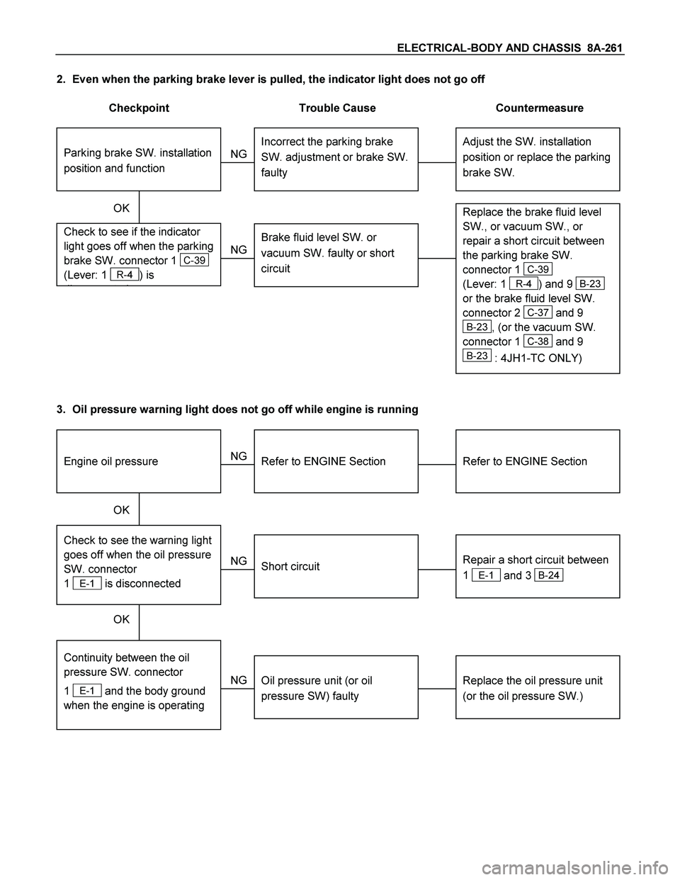
2. Even when the parking brake lever is pulled, the indicator light does not go off
Checkpoint Trouble Cause Countermeasure
Adjust the SW. installation
position or replace the parking
brake SW. Incorrect the parking brake
SW. adjustment or brake SW.
faulty
NG Thermo unit malfunction
Replace the brake fluid level
SW., or vacuum SW., or
repair a short circuit between
the parking brake SW.
connector 1
C-39
(Lever: 1
R-4) and 9 B-23
or the brake fluid level SW.
connector 2
C-37 and 9
B-23, (or the vacuum SW.
connector 1
C-38 and 9
B-23 : 4JH1-TC ONLY)
Check to see if the indicator
light goes off when the parking
brake SW. connector 1
C-39
(Lever: 1
R-4) is
di t d
Brake fluid level SW. or
vacuum SW. faulty or short
circuit
NG OK
Parking brake SW. installation
position and function
3. Oil pressure warning light does not go off while engine is running
Refer to ENGINE Section
Refer to ENGINE Section
NG Thermo unit malfunction
Repair a short circuit between
1
E-1 and 3 B-24
Check to see the warning light
goes off when the oil pressure
SW. connector
1
E-1 is disconnected
Short circuit
Replace the oil pressure unit
(or the oil pressure SW.)
Continuity between the oil
pressure SW. connector
1
E-1 and the body ground
when the engine is operating
Oil pressure unit (or oil
pressure SW) faulty
NG NG OK
OK
Engine oil pressure
Page 921 of 4264
ELECTRICAL-BODY AND CHASSIS 8A-263
WARNING LIGHT BULB, INDICATOR
LIGHT BULB AND ILLUMINATION LIGHT
BULB
Removal
Turn the bulb socket counterclockwise and pull the bulb out.
Installation
To Install, follow the removal steps in the reverse order.
FUEL TANK UNIT
Removal
Dismount the fuel tank first, then remove the fuel tank unit.
1. Remove the rear inner liner -LH
� Remove the clip
2. Remove the filler neck.
� Remove the screw
3. Remove the ground with cable.
4. Remove the fuel tank band.
� T/M jack unit on the vehicle.
� Disconnect fuel line quick connectors.
5. Remove the fuel tank unit from the fuel tank.
Page 923 of 4264
ELECTRICAL-BODY AND CHASSIS 8A-265
INSPECTION AND REPAIR
Warning, indicator and illumination light position
Without tachometer (C24NE)
RTW38AXF026601
Page 936 of 4264

8A-278 ELECTRICAL-BODY AND CHASSIS
Low Fuel Indicator Light Inspection
1. Disconnect the fuel tank unit wire connector.
2. Turn the key switch on. Check that the bulb lights.
If operation is not correct, remove and check the bulb or circuit.
or If check whether low fuel turns on fuel input (B-24) at the
time of open and key on.
� meter is check at low fuel
140R300006
Check level sensor operation
1. Remove the fuel tank unit.
2.
Apply battery voltage between terminal (B) and (C) through
a 1.12 watt bulb. Check that the bulb lights.
Note:
It will take a short time for the bulb light.
3. Submerge the sensor in fuel. Check that the bulb goes out.
If operation is not correct, replace the fuel tank unit.
BRAKE SYSTEM WARNING LIGHT
The brake system warning light comes on while the parking
brake is set and the engine run position.
Note:
The parking brake indicator light circuit is designed to
prevent driving of the vehicle with the parking brake on.
It does not indicate the condition of the parking brake
system.
The parking brake switch is in parallel with the brake fluid
switch.
The brake system warning light also comes on when reservoir
brake fluid level falls below the specified limit with the parking
brake released and the engine run position.
Page 1101 of 4264

CRUISE CONTROL SYSTEM 8B-3
Service Precaution
WARNING: THIS VEHICLE HAS A SUPPLEMENTAL RESTRAIN SYSTEM (SRS). REFER TO THE SRS
COMPONENT AND WIRING LOCATION VIEW IN ORDER TO DETERMINE WHETHER YOU ARE
PERFORMING SERVICE ON OR NEAR THE SRS COMPONENTS OR THE SRS WIRING. WHEN YOU ARE
PERFORMING SERVICE ON OR NEAR THE SRS COMPONENTS OR THE SRS WIRING, REFER TO THE SRS
SERVICE INFORMATION. FAILURE TO FOLLOW WARNINGS COULD RESULT IN POSSIBLE AIR BAG
DEPLOYMENT, PERSONAL INJURY, OR OTHER WISE UNNEEDED SRS SYSTEM REPAIRS.
CAUTION: Always use the correct fastener in the proper location. When you replace a faster, use ONLY the
exact part number for that application. Dealer will call out those fasteners that require a replacement after
removal. Dealer will also call out the fasteners that require thread lockers or thread sealant. UNLESS
OTHERWISE SPECIFIED, do not use supplemental coatings (Paints, greases, or other corrosion inhibitors)
on threaded fasteners or fastener joint interfaces. Generally, such coatings adversely affect the fastener
torque and joint Clamping force, and may damaged the fastener. When you install fasteners, use the
correct tightening sequence and specifications. Following these instructions can help you avoid damage to
parts and systems.
General Description
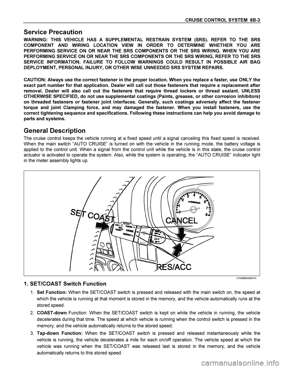
The cruise control keeps the vehicle running at a fixed speed until a signal canceling this fixed speed is received.
When the main switch “AUTO CRUISE” is turned on with the vehicle in the running mode, the battery voltage is
applied to the control unit. When a signal from the control unit while the vehicle is in this state, the cruise control
actuator is activated to operate the system. Also, while the system is operating, the “AUTO CRUISE” indicator light
in the meter assembly lights up.
LTW48BSH000101
1. SET/COAST Switch Function
1. Set Function: When the SET/COAST switch is pressed and released with the main switch on, the speed at
which the vehicle is running at that moment is stored in the memory, and the vehicle automatically runs at the
stored speed.
2. COAST-down Function: When the SET/COAST switch is kept on while the vehicle in running, the vehicle
decelerates during that time. The speed at which vehicle is running when the control switch is pressed in the
memory, and the vehicle automatically returns to the stored speed.
3. Tap-down Function: When the SET/COAST switch is pressed and released instantaneously while the
vehicle is running, the vehicle decelerates a mile for each on/off operation. The vehicle speed at which the
vehicle was running when the SET/COAST was released last is stored in the memory, and the vehicle
automatically returns to this stored speed.
Page 1108 of 4264

8B-10 CRUISE CONTROL SYSTEM
Diagnosis
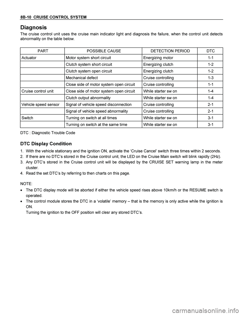
The cruise control unit uses the cruise main indicator light and diagnosis the failure, when the control unit detects
abnormality on the table below.
PART POSSIBLE CAUSE DETECTION PERIOD DTC
Actuator Motor system short circuit Energizing motor 1-1
Clutch system short circuit Energizing clutch 1-2
Clutch system open circuit Energizing clutch 1-2
Mechanical defect Cruise controlling 1-3
Close side of motor system open circuit Cruise controlling 1-1
Cruise control unit Close side of motor system open circuit While starter sw on 1-4
Clutch output abnormality While starter sw on 1-4
Vehicle speed sensor Signal of vehicle speed disconnection Cruise controlling 2-1
Signal of vehicle speed abnormality Cruise controlling 2-1
Switch Turning on switch at all times While starter sw on 3-1
Turning on switch at the same time While starter sw on 3-1
DTC : Diagnostic Trouble Code
DTC Display Condition
1. With the vehicle stationary and the ignition ON, activate the ‘Cruise Cancel’ switch three times within 2 seconds.
2. If there are no DTC’s stored in the Cruise control unit, the LED on the Cruise Main switch will blink rapidly (2Hz).
3. Any DTC’s stored in the Cruise control unit will be displayed by the CRUISE SET warning lamp in the meter
cluster.
4. Read the set DTC’s by referring to then charts on this page.
NOTE:
� The DTC display mode will be aborted if either the vehicle speed rises above 10km/h or the RESUME switch is
operated.
� The control module stores the DTC in a ‘volatile’ memory – that is the memory is only active while the ignition is
ON.
Turning the ignition to the OFF position will clesr any stored DTC’s.
Page 1181 of 4264

ENGINE MECHANICAL 6A – 41
Coolant Replenishment
Warning:
When the coolant is heated to a high temperature, be
sure not to loosen or remove the rediator cap.
Otherwise you might get scalded by hot vapor or
boiling water.
To open the radiator cap, put a piece of thick cloth on
the cap and loosen the cap slowly to reduce the
pressure when the coolant has become cooler.
1. Open rediator cap pour coolant up to filler neck
2. Pour coolant into reservoir tank up to "MAX" line
3. Tighten radiator cap and start the engine. After idling
for 2 to 3 minutes, stop the engine and reopen radiator
cap. If the water level is lower, replenish.
4. After replenish the coolant tighten radiator cap, warm
up the engine at about 2000 rpm. Set heater
adjustment to the highest temperature position, and let
the coolant circulate also into heater water system.
5. Check to see the thermometer, continuously idling 5
minutes and stop the engine.
6. When the engine has been cooled, check filler neck for
water level and replenish if required. Should extreme
shortage of coolant is found, check the coolant system
and reservoir tank hose for leakage.
7. Pour coolant into the reservoir tank up to "MAX" line.
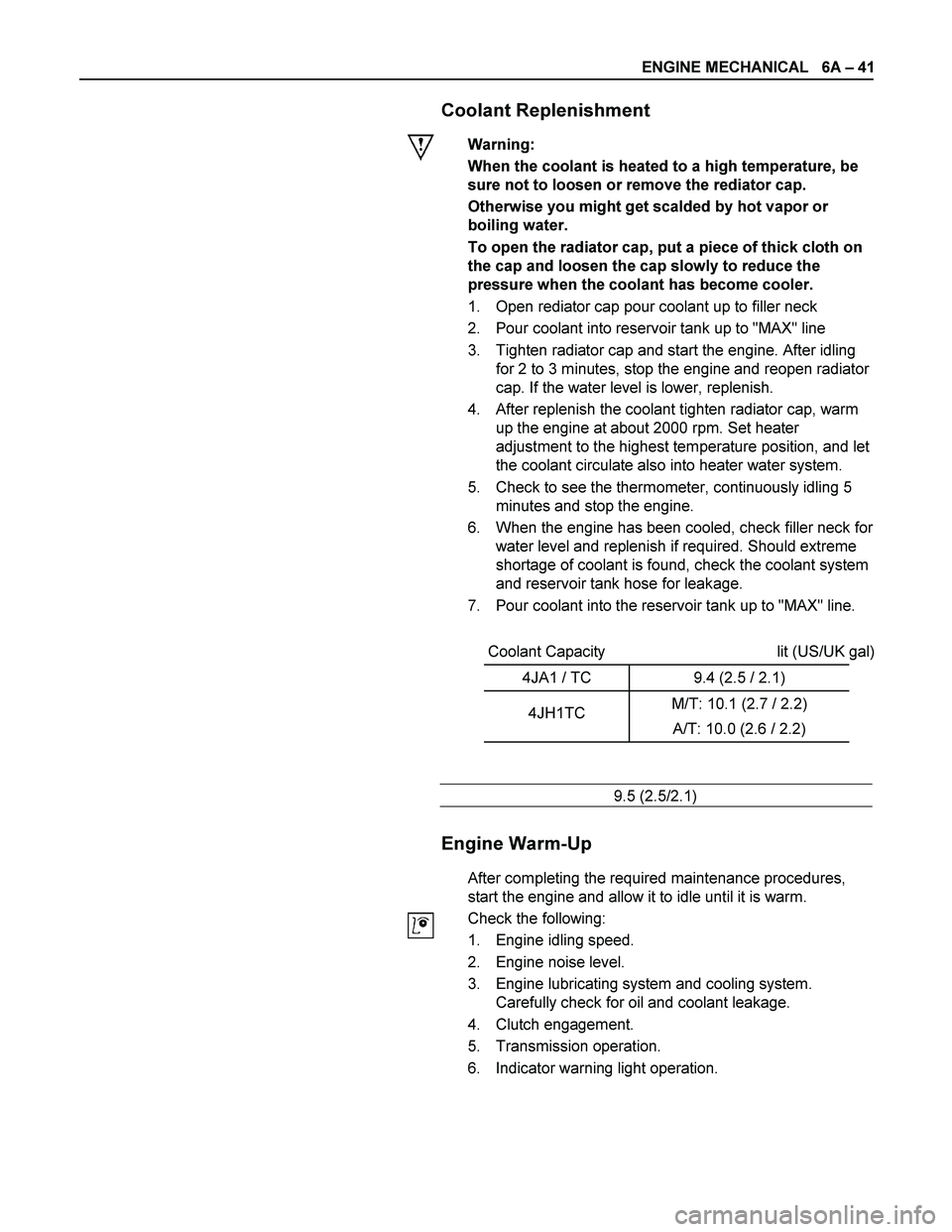
Coolant Capacity lit (US/UK gal)
4JA1 / TC 9.4 (2.5 / 2.1)
4JH1TC M/T: 10.1 (2.7 / 2.2)
A/T: 10.0 (2.6 / 2.2)
9.5 (2.5/2.1)
Engine Warm-Up
After completing the required maintenance procedures,
start the engine and allow it to idle until it is warm.
Check the following:
1. Engine idling speed.
2. Engine noise level.
3. Engine lubricating system and cooling system.
Carefully check for oil and coolant leakage.
4. Clutch engagement.
5. Transmission operation.
6. Indicator warning light operation.