UNIT REPAIR (JR405E) 7A4-15
244L300003
Legend
1. High clutch oil pressure switch connector
(wire color: Gray)
2. 2-4 brake oil pressure switch connector
(wire color: Brown)
3. Low and reverse brake oil pressure
switch connector (wire color: White)
4. Low and reverse brake duty solenoid
connector (wire color: Pink and White)
5. High clutch duty solenoid connector
(wire color: Green and Gray)
6. Lock-up duty solenoid connector (wire
color: Yellow and Black)
7. 2-4 brake duty solenoid connector (wire
color: Blue and Brown)
8. Low clutch duty solenoid connector (wire
color: Orange and Black)
9. Line pressure solenoid connector (wire
color: Pink)
7A4-16 UNIT REPAIR (JR405E)
12CV19
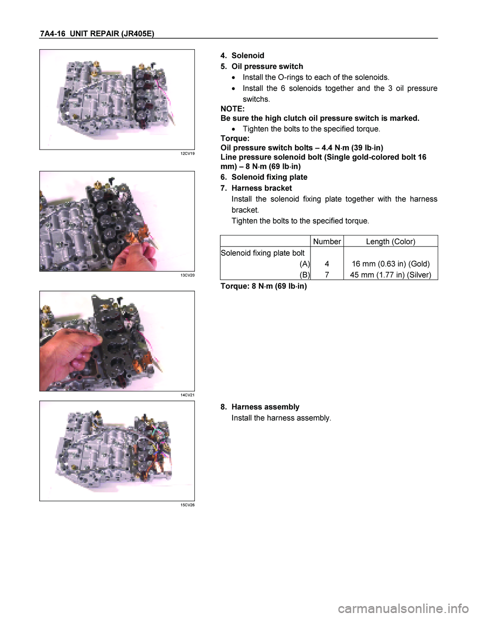
4. Solenoid
5. Oil pressure switch � Install the O-rings to each of the solenoids.
� Install the 6 solenoids together and the 3 oil pressure
switchs.
NOTE:
Be sure the high clutch oil pressure switch is marked.
� Tighten the bolts to the specified torque.
Torque:
Oil pressure switch bolts – 4.4 N �
��
�
m (39 Ib �
��
�
in)
Line pressure solenoid bolt (Single gold-colored bolt 16
mm) – 8 N �
��
�
m (69 Ib �
��
�
in)
6. Solenoid fixing plate
7. Harness bracket Install the solenoid fixing plate together with the harness
bracket.
Tighten the bolts to the specified torque.
Number Length (Color)
Solenoid fixing plate bolt
(A) 4 16 mm (0.63 in) (Gold)
(B) 7 45 mm (1.77 in) (Silver)
13CV20
Torque: 8 N �
��
�
m (69 Ib �
��
�
in)
14CV21
15CV26
8. Harness assembly
Install the harness assembly.
UNIT REPAIR (JR405E) 7A4-23
CONTROL VALVE LOWER BODY
10CV11
Legend
1. Retainer plate, spring, and steel ball
2. Retainer plate, plug, spring, and
pressure regulator valve
3. Retainer plate, spring, and high clutch
accumulator
4. Retainer plate, plug, low and reverse
brake fail valve A, and spring
5. Retainer plate, plug, spring, and fail
valve
6. Retainer plate, plug, low and reverse
brake amp valve, and spring
7. Oil pressure switch
8. Oil filter
9. Solenoid
10. Line pressure solenoid
11. Lock-up solenoid
12. Harness bracket
13. Solenoid fixing plate
14. Harness assembly
15. Retainer plate, plug, spring, and 2-4
brake fail valve A
16. Retainer plate, plug, spring, and low
clutch amp valve B
17. Retainer plate, spring, and torque
converter relief valve
18. Oil strainer
19. Control valve lower body
20. Retainer plate, spring, and 2-4 brake
solenoid accumulator
21. Oil pressure switch
UNIT REPAIR (JR405E) 7A4-27
Spring specifications
No. Valve nomenclature Free length
(mm / in) Outside
diameter (mm
/ in) Linear
diameter (mm
/ in) Number of
coils
14 Pressure relief 49.0 / 1.929 7.6 / 0.299 1.1 / 0.043 17.3
15 Pressure regulator 30.5 / 1.201 14.0 / 0.551 1.4 / 0.055 5.7
16 Low and reverse brake fail (A) 22.0 / 0.866 7.0 / 0.276 0.6 / 0.024 10.0
17 Fail 23.0 / 0.906 11.0 / 0.433 0.5 / 0.020 13.2
18 Low and reverse brake amp 19.5 / 0.768 7.9 / 0.311 0.5 / 0.020 6.9
19 2 – 4 brake fail (A) 24.8 / 0.976 8.5 / 0.335 0.9 / 0.035 7.8
20 Low clutch amp (B) 26.0 / 1.024 11.0 / 0.433 0.5 / 0.020 6.9
21
Torque converter relief More than 47.2
/ 1.858 9.2 / 0.362 1.6 / 0.063 20.2
22 2 – 4 brake solenoid accumulator 31.4 / 1.236 9.8 / 0.386 1.3 / 0.051 9.3
23 High clutch accumulator 51.0 / 2.008 6.5 / 0.256 0.8 / 0.031 23.5
Oil pressure switch
Apply compressed air (392 kPa/4.0 kg/cm2) to the oil pressure
switch to check the oil pressure switch continuity between the
connector and screw.
244L300011
Oil temperature sensor (harness assembly)
Check the oil temperature sensor resistance between harness
terminals 7 and 6 (ground).
Oil temperature sensor resistance: 2,400�
�� �2,600 ohms
(20�
�� �)
Solenoid
Measure the resistance of each solenoid.
Resistance:
Brown connector – 3.0�
�� �3.4 ohms (20�
�� �C)
Gray connector – 12.0�
�� �13.2 ohms (20�
�� �C)
White connector – 12.2�
�� �13.4 ohms (20�
�� �C)
Reassembly steps
� Coat the parts with ATF before installing them.
� Install the control valve to the control valve lower body.
� Install the oil filter to the control valve lower body.
 7A4-15
244L300003
Legend
1. High clutch oil pressure switch connector
(wire color: Gray)
2. 2-4 brake oil pressure switch connector
(wire color: Brown)
3. Low and r")
 7A4-23
CONTROL VALVE LOWER BODY
10CV11
Legend
1. Retainer plate, spring, and steel ball
2. Retainer plate, plug, spring, and
pressure regulator valve
3. Retain")
 7A4-27
Spring specifications
No. Valve nomenclature Free length
(mm / in) Outside
diameter (mm
/ in) Linear
diameter (mm
/ in) Number of
coils
14 Pressure relief 49.")