Page 3513 of 4264
FRONT SUSPENSION 3C-21
Lower Control Arm
Lower Control Arm and Associated Parts
RTW340LF002301
Legend
(1)
Cam bolt
(2)
Bush
(3)
Cam plate
(4)
Nut
(5)
Nut
(6)
Bolt
(7)
Lower Ball Joint
(8)
Nut and cotter pin
(9)
Nut
(10) Nut
(11) Bolt
Removal
1. Raise the vehicle and support the frame with
suitable safety stands.
2. Remove wheel and tire assembly. Refer to Wheel
in this section.
3. Remove the tie-rod end from the knuckle. Refer to
Power Steering Unit in Steering section.
Page 3528 of 4264
3C-36 FRONT SUSPENSION
� Rubber seat
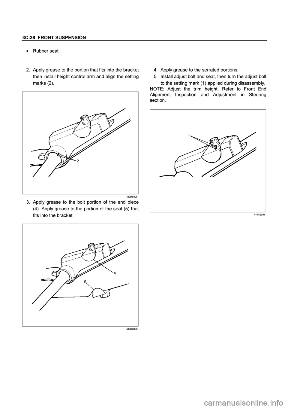
2.
Apply grease to the portion that fits into the bracket
then install height control arm and align the setting
marks (2).
410RS005
3. Apply grease to the bolt portion of the end piece
(4). Apply grease to the portion of the seat (5) that
fits into the bracket.
410RS008
4. Apply grease to the serrated portions.
5. Install adjust bolt and seat, then turn the adjust bolt
to the setting mark (1) applied during disassembly.
NOTE: Adjust the trim height. Refer to Front End
Alignment Inspection and Adjustment in Steering
section.
410RS004
Page 3530 of 4264
3C-38 FRONT SUSPENSION
4. Remove the hub assembly. Refer to Front Hub
and Disk in this section.
5. Remove tie-rod end from the knuckle. Refer to
Power Steering Unit in Steering section.
6. Remove the speed sensor from the knuckle.
7. Loosen torsion bar by height control arm adjust
bolt, then remove torsion bar. Refer to Torsion Ba
r
in this section.
8. Remove speed sensor harness.
9. Remove back plate.
10. Remove lower ball joint by using remover 5-8840-
2005-0.
CAUTION: Be careful not to damage the ball joint
boot.
901RW271
11. Remove upper ball joint by using remover 5-8840-
2121-0.
CAUTION: Be careful not to damage the ball joint
boot.
901RW272
12. Remove knuckle assembly.
13. Remove oil seal. If replacement required.
(4�
4 Model Only)
14. Remove washer. If replacement required.
(4�
4 Model Only)
15. Remove needle bearing by using remover 5-8840-
2000-0 and sliding hammer 5-8840-0019-0.
If replacement required. (4�
4 Model Only)
(4�
4 Model Only)
RTW340SH00401
Page 3531 of 4264

FRONT SUSPENSION 3C-39
Inspection and Repair
Make necessary correction or parts replacement if
wear, damage, corrosion or any other abnormal
condition are found through inspection.
Check the following parts:
�
Knuckle
�
Knuckle arm
� Thrust washer (4�4 Model Only)
Installation
1. Apply appropriate amount of multipurpose type
grease to the new bearing (Approx. 5 g) and
install needle bearing by using installer 5-8840-
2128-0 and grip 5-8840-0007-0. (4�
4 Model Only)
(4�4 Model Only)
901RW275
2. Apply multipurpose type grease to the thrust
washer, and install washer with chamfered side
facing knuckle. (4�4 Model Only)
3. Use a new oil seal, and apply multipurpose type
grease to the area surrounded by the lip (approx. 2
g). Then use installer 5-8840-2127-0 and grip 5-
8840-0007-0 to install oil seal. After fitting the oil
seal to the installer, drive it to the knuckle using a
hammer or bench press until the tool front face
contacts with the thrust washer. (4�
4 Model Only)
(4�4 Model Only)
901RW274
4. Install knuckle assembly.
5. Install upper ball joint and tighten the nut to the
specified torque, with just enough additional torque
to align cotter pin holes. Install new cotter pin (9).
Torque: 98 N�
�� �m (10.0kg�
�� �m/72 lb ft)
6. Install lower ball joint and tighten the nut to the
specified torque, with just enough additional torque
to align cotter pin holes. Install new cotter pin (2).
Torque: 147 N
�
�� �m (15.0kg
�
�� �m/108 lb ft)
7. Install back plate.
8. Install speed sensor harness.
9. Install torsion bar, refer to Torsion Bar in this
section.
NOTE: Adjust the trim height. Refer to Front End
Alignment Inspection and Adjustment in Steering.
Page 3537 of 4264

FRONT SUSPENSION 3C-45
Removal
1. Raise the vehicle and support the frame with
suitable safety stands.
2. Remove wheel and tire assembly. Refer to Wheel
in this section.
3. Remove the tie-rod end from the knuckle. Refer to
Power Steering Unit in Steering section.
4. Remove the retaining ring from the front axle
driving shaft to release the shaft from hub. Refer to
Front Hub and Disc in Driveline/Axle section.
5. Support lower control arm with a jack.
6. Remove cam plate and nut.
7. Remove rear nut.
8. Remove torsion bar, refer to Torsion Bar in this
section.
9. Remove torsion bar arm bracket.
10. Disconnect the stabilizer link at the lower control
arm.
11. Remove the shock absorber lower end from the
lower control arm.
12. Remove the lower ball joint from the lower control
arm.
13. Remove cam bolt.
14. Remove rear bolt.
15. Remove lower control arm.
16. Remove torsion bar arm bolt.
17. Remove lower ball joint bolt.
18. Remove front bushing by using remover 5-8840-
2123-0.
Front
901RW154
Front
901RW155
19. Remove rear bushing by using remover 5-8840-
2124-0.
Front
901RW051
Front
901RW052
Page 3539 of 4264
FRONT SUSPENSION 3C-47
14. Install cam plate and nut then tighten lower link nut
finger-tight.
NOTE: Apply oil to the thread.
NOTE: Tighten the nut (3) or bolt with the parts in the
position shown in the illustration below.
Buffer clearance: 29.7 mm (1.17 in)
Torque: 186 N�
�� �m (19.0kg�
�� �m/137 lb ft)
NOTE: Adjust the trim height. Refer to Front En
d
Alignment Inspection and Adjustment in Steering
section.
450R100002
Page 3542 of 4264
3C-50 FRONT SUSPENSION
Lower Ball Joint
Lower Ball Joint and Associated Parts
RTW340LF001601
Legend
(1)
Bolt
(2)
Lower Ball Joint
(3) Nut
(4)
Nut and Cotter Pin
Removal
1. Raise the vehicle and support the frame with
suitable safety stands.
2. Remove wheel and tire assembly. Refer to Wheel
in this section.
3. Remove the tie-rod end from the knuckle. Refer to
Power Steering Unit in Steering section.
4. Remove the retaining ring from the front axle
driving shaft to release the shaft from hub. Refer to
Front Hub and Disc in Driveline/Axle section.
5. Support lower control arm with a jack.
6. Remove lower ball joint nut and cotter pin, then
use remover 5-8840-2005-0 to remove the lowe
r
ball joint from the knuckle.
Page 3546 of 4264

3C-54 FRONT SUSPENSION
TROUBLESHOOTING
1. VIBRATION, SHOCK, AND SHIMMY OF STEERING WHEEL
Checkpoint Trouble Cause Countermeasure
Check front axle
Check wheel alignment
Check suspension ball joint
Check shock absorber or
attaching nut and bolt
Replace
Adjust
Replace
Replace or retighten
Check steering unit and
linkage
Faulty
Worn
Malfunction or loose
Check upper and lower link
bushings
Replace
Adjust
Worn
Incorrect
OK OK OK
NG NG NG NG NG NG
OK OK
Check vehicle trim height
�
Improperly adjusted or worn front
wheel bearing.
�
Worn or incorrectl
y adjusted wheel
bearing.
Replace; refer to Section 4C "Front
Wheel Drive"
�
Insufficientl
y tightened steeringgear housing.
�
Wear of steering linkage.
�
Excessive backlash due to
improper ad
justment of the steeringgear box.
� Worn column bearing weakened
column bearing spring, or loose
clamp.
Replace; refer to Section 3B
"Steering"
�
Improper tire pressure.
� Imbalance and deformation of frond
wheel.
�
Unevenl
y worn tire or insufficient
tightening of wheel nuts.
Replace; refer to Section 3E "Wheel
and Tires"

Cam bolt
(2)
Bush
(3)
Cam plate
(4)
Nut
(5)
Nut
(6)
Bolt")

 or bolt with the parts in the
position sho")

Bolt
(2)
Lower Ball Joint
(3) Nut
(4)
Nut and Cotter Pin
Rem")