Page 3418 of 4264

3A-2 FRONT ALIGNMENT
Front End Alignment Inspection and
Adjustment
General Description
“Front End Alignment” refers to the angular
relationshipbetween the front wheels, the front suspension
attachingparts and the ground.
Proper front end alignment must be maintained in order
toinsure efficient steering, good directional stability and
toprevent abnormal tire wear.
The most important factors of front end alignment arewheel
toe-in, wheel camber and axle caster.
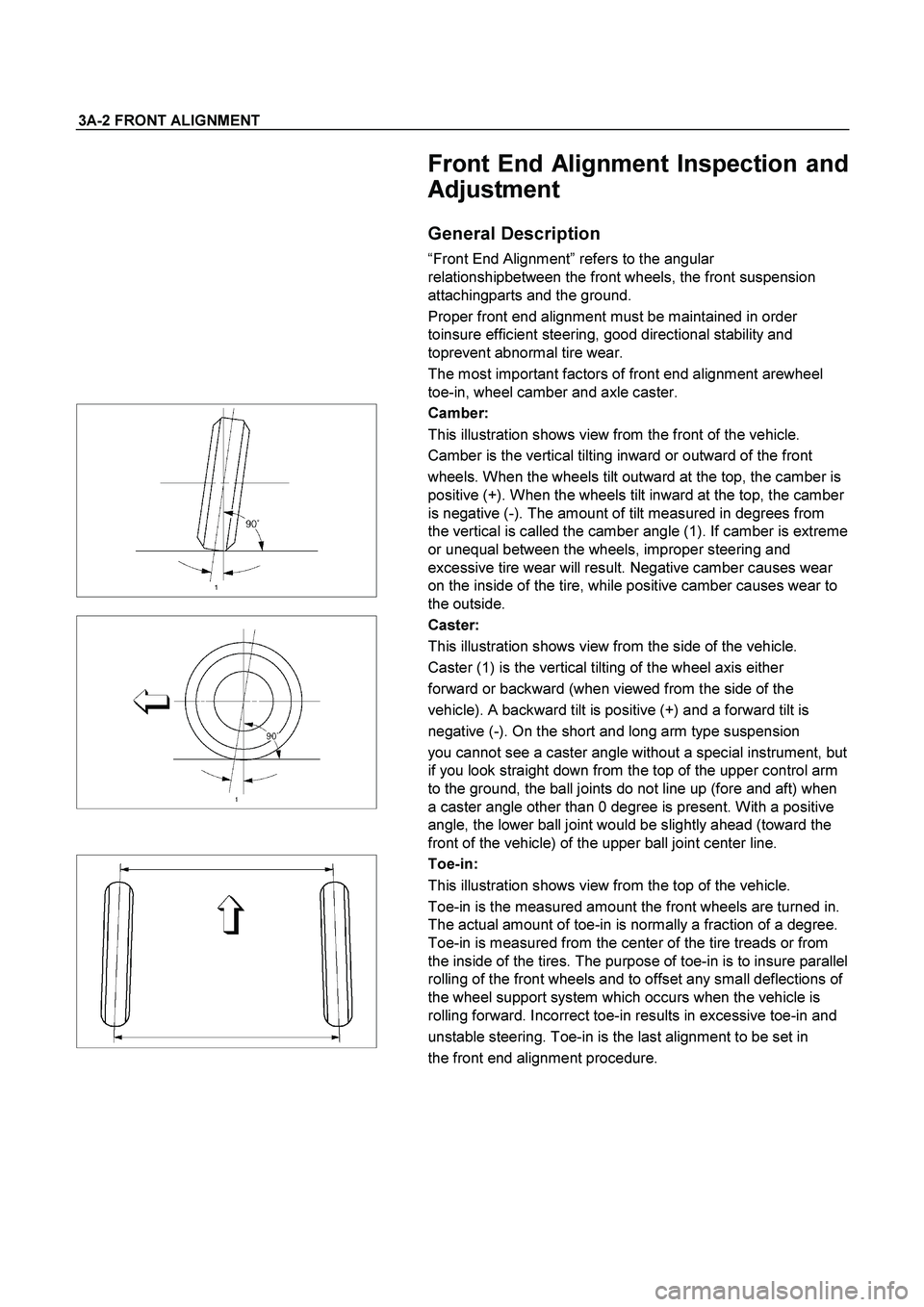
Camber:
This illustration shows view from the front of the vehicle.
Camber is the vertical tilting inward or outward of the front
wheels. When the wheels tilt outward at the top, the camber is
positive (+). When the wheels tilt inward at the top, the camber
is negative (-). The amount of tilt measured in degrees from
the vertical is called the camber angle (1). If camber is extreme
or unequal between the wheels, improper steering and
excessive tire wear will result. Negative camber causes wear
on the inside of the tire, while positive camber causes wear to
the outside.
Caster:
This illustration shows view from the side of the vehicle.
Caster (1) is the vertical tilting of the wheel axis either
forward or backward (when viewed from the side of the
vehicle). A backward tilt is positive (+) and a forward tilt is
negative (-). On the short and long arm type suspension
you cannot see a caster angle without a special instrument, but
if you look straight down from the top of the upper control arm
to the ground, the ball joints do not line up (fore and aft) when
a caster angle other than 0 degree is present. With a positive
angle, the lower ball joint would be slightly ahead (toward the
front of the vehicle) of the upper ball joint center line.
Toe-in:
This illustration shows view from the top of the vehicle.
Toe-in is the measured amount the front wheels are turned in.
The actual amount of toe-in is normally a fraction of a degree.
Toe-in is measured from the center of the tire treads or from
the inside of the tires. The purpose of toe-in is to insure parallel
rolling of the front wheels and to offset any small deflections of
the wheel support system which occurs when the vehicle is
rolling forward. Incorrect toe-in results in excessive toe-in and
unstable steering. Toe-in is the last alignment to be set in
the front end alignment procedure.
Page 3580 of 4264

3E-8 WHEELS AND TIRES
INSPECTION AND REPAIR
Make necessary correction or parts replacement if wear, damage or any other abnormal conditions are found
through inspection.
Visual Check
Inspect all disassembled parts for wear, damage or other
abnormal conditions.
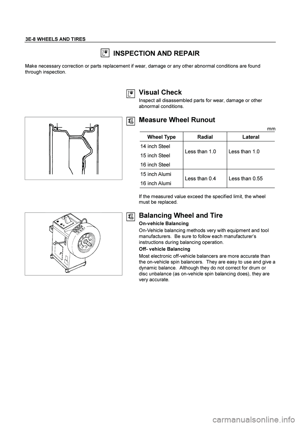
Measure Wheel Runout
mm
Wheel Type Radial Lateral
14 inch Steel
15 inch Steel
16 inch Steel Less than 1.0 Less than 1.0
15 inch Alumi
16 inch Alumi Less than 0.4 Less than 0.55
If the measured value exceed the specified limit, the wheel
must be replaced.
Balancing Wheel and Tire
On-vehicle Balancing
On-Vehicle balancing methods very with equipment and tool
manufacturers. Be sure to follow each manufacturer’s
instructions during balancing operation.
Off- vehicle Balancing
Most electronic off-vehicle balancers are more accurate than
the on-vehicle spin balancers. They are easy to use and give a
dynamic balance. Although they do not correct for drum or
disc unbalance (as on-vehicle spin balancing does), they are
very accurate.
Page 3690 of 4264

7A2-10 TRANSMISSION CONTROL SYSTEM (AW30 –40LE) (V6 3.5L)
Control and Functions
Shift Control
The transmission gear is shifted according to the shift
pattern selected by the driver. In shifting gears, the
gear ratio is controlled by the ON/ OFF signal using the
shift solenoid S1 and the shift solenoid S2.
Band Apply Control
The band apply is controlled when in the 3 –2 downshift
(engine overrun prevention) and the garage shift (shock
control).
The band apply solenoid is controlled by the signal from
the Pulse Width Modulation (PWM) to regulate the flow
of the oil.
Torque Converter Clutch Control
The clutch ON/OFF is controlled by moving the
converter clutch valve through shifting Torque
Converter Clutch (TCC) solenoid using the ON/OFF
signal.
Line Pressure Control
The throttle signal allows the current signal to be sent
to the force motor. After receiving the current signal,
the force motor activates the pressure regulator valve
to regulate the line pressure.
On –Board Diagnostic System
Several malfunction displays can be stored in the
Transmission Control Module (TCM) memory, and read
out of it afterward.
The serial data lines, which are required for the testing
of the final assembly and the coupling to othe
r
electronic modules, can be regulated by this function.
Fail –Safe Mechanism
If there is a problem in the transmission system, the
TCM will go into a “backup" mode.
The vehicle can still be driven, but the driver must use
the select lever to shift gears.
Torque Management Control
The transmission control side sends the absolute spark
advance signal to the engine control side while the
transmission is being shifted. This controls the engine
spark timing in compliance with the vehicle running
condition to reduce the shocks caused by the change o
f
speed.
ATF Warning Control
The oil temperature sensor detects the ATF oil
temperature to control the oil temperature warning,
TCC, and the 3rd start mode.
Reverse Lock Out Control
With the selector lever in reverse position, the TCM will
not close the PWM solenoid until the vehicle is below
15 km/h (9.3 mph), thus preventing reverse
engagement above this speed.
Downhill Control
This mode is automatically activated from NORMAL
mode only when downhill conditions are recognized.
The shift pattern is identical to NORMAL mode except
3-4 and 4-3 shift lines at low throttle modified to get
engine braking on a larger speed range.
Uphill Control
When uphill condition are recognized the 2-3 and 3-4
shift and TCC apply are down only when the engine
torque is sufficient in order to avoid shift hunting.
Gear Shift Control 3rd start
SELECT LEVER RANGE SHIFT PATTERN
D(Drive) 1
�
2TCC �
3TCC �
4TCC
3(Third) 1 �
2TCC �
3TCC
2(Second) 1 �
2(�3)
L(First) 1(�2)
TCC: Torque Converter Clutch
(Notice1): “( )" means over-revving prevention control.
Mode Type
Mode Type Select lever position
Normal drive mode
(NOR) Entire range (excluding “R")
Power drive mode
(PWR) Entire range (excluding “R")
Mode Selection
SWITCH(SW) LAMP
Mode Type PWR/N
OR.S 3RD
START SW POWER
DRIVE LAMP 3RD
START LAMP
Normal
drive mode
(NOR) OFF OFF OFF OFF
Power
drive mod
(PWR) ON OFF ON OFF
3rd Start
mode OFF ON OFF ON
However, the 3rd start switch prevails over the
PWR/NOR switch.
The mode become normal drive mode when the 3rd
start switch is operated from ON to OFF.