Page 2809 of 4264

NOTE: The replacement ECM must be programmed. Refer to")
ENGINE DRIVEABILITY AND EMISSIONS 6E–233
ENGINE CRANKS BUT WILL NOT RUN
DEFINITIONS: Engine cranks, but will not run. (The engine never start.)
NOTE: The replacement ECM must be programmed. Refer to section of the Service Programming System (SPS) in
this manual. Following ECM programming, the immobilizer system (if equipped) must be linked to the ECM.
Refer to section 11 “Immobilizer System-ECM replacement” for the ECM/Immobilizer linking procedure.
NOTE: The vehicle with immobilizer system, this system may be activated. Check the immobilizer system diagosis.
Step Action Value(s) Yes No
1Was the “On-Board Diagnostic (OBD) System Check”
performed?—Go to Step 2Go to OBD
System Check
2 1. Perform a bulletin search.
2. If a bulletin that addresses the symptom is found,
correct the condition as instructed in the bulletin.
Was a bulletin found that addresses the symptom?—Verify repair Go to Step 3
3 Was a visually/physical check performed?
—Go to Step 4Go to Visual /
physical Check.
4 Check the “Ignition coil” fuse (15A) and “ECM” fuse
(15A).
Was a fuse blown?—Verify repair Go to Step 5
5 1. Ignition ON
2. Use a DVM to verify that battery voltage at the
ignition coil fuse, and the ECM fuse.
Was battery voltage presented at the fuses?—Go to Step 6Verify & repair
6 1. Visually/physically inspect for the following
conditions:
Restriction of air intake system. Check for a
restricted air filter element, or foreign objects
blocking the air intake system.
Check for objects blocking the IAC passage or
throttle bore, excessive deposits in the throttle
bore and on the throttle plate.
Check for a condition that causes a large
vacuum leak, such as an incorrectly installed or
faulty crankcase ventilation hose/brake booster
hose.
Was a problem found?—Verify repair Go to Step 7
7 1. Using a Tech 2, display the IAC value.
2. Check for a faulty, plugged, or sticking IAC
operation.
Was the problem found?—Verify repair Go to Step 8
8 1. Using a Tech 2, display the MAP sensor value.
2. Check for a faulty, plugged, or incorrectly installed
MAP sensor.
Was the problem found?—Verify repair Go to Step 9
9 If oscilloscope is available, check the wave form of the
CKP signal.
Was the correct wave form found?—Go to Step 12Go to Step 10
10 Check the CKP sensor wire for open or short circuit.
Was a problem found?—Verify repair Go to Step 11
11 Replace CKP sensor.
Is there still problem?—Replace pulsar
ring. Verify repair
Page 3100 of 4264
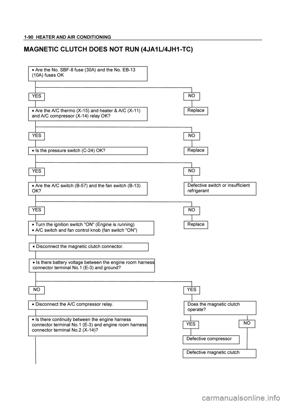
1-90 HEATER AND AIR CONDITIONING
MAGNETIC CLUTCH DOES NOT RUN (4JA1L/4JH1-TC)
Replace
YES
�
Are the A/C thermo (X-15) and heater & A/C (X-11)
and A/C compressor (X-14) relay OK?
� Are the No. SBF-8 fuse (30A) and the No. EB-13
(10A) fuses OK
YES
�
Is the pressure switch (C-24) OK?
YES
�
Are the A/C switch (B-57) and the fan switch (B-13)
OK?
NO
YES
�
Is there continuity between the engine harness
connector terminal No.1 (E-3) and engine room harness
connector terminal No.2 (X-14)?
� Disconnect the A/C compressor relay.
� Turn the ignition switch "ON" (Engine is running)
�
A/C switch and fan control knob (fan switch "ON")
NO
Replace
NO
Defective switch or insufficient
refrigerant
NO
NO
Does the magnetic clutch
operate?
YES
Replace
�
Disconnect the magnetic clutch connector.
� Is there battery voltage between the engine room harness
connector terminal No.1 (E-3) and ground?
Defective compressor
YESNO
Defective magnetic clutch
Page 3105 of 4264
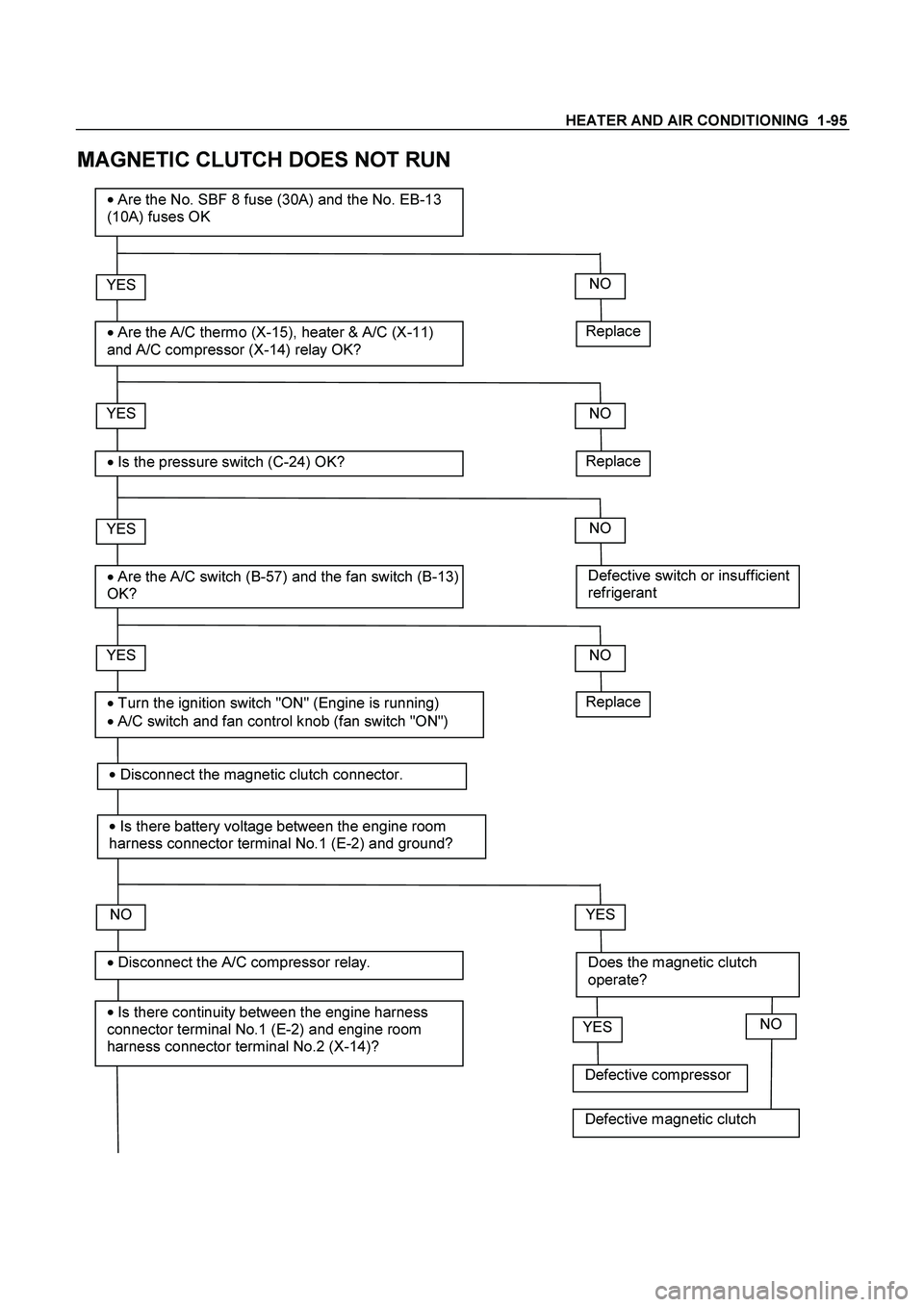
HEATER AND AIR CONDITIONING 1-95
MAGNETIC CLUTCH DOES NOT RUN
Replace
YES
� Are the A/C thermo (X-15), heater & A/C (X-11)
and A/C compressor (X-14) relay OK?
�
Are the No. SBF 8 fuse (30A) and the No. EB-13
(10A) fuses OK
YES
� Is the pressure switch (C-24) OK?
YES
�
Are the A/C switch (B-57) and the fan switch (B-13)
OK?
NO
YES
�
Is there continuity between the engine harness
connector terminal No.1 (E-2) and engine room
harness connector terminal No.2 (X-14)?
�
Disconnect the A/C compressor relay.
�
Turn the ignition switch "ON" (Engine is running)
� A/C switch and fan control knob (fan switch "ON")
NO
Replace
NO
Defective switch or insufficient
refrigerant
NO
NO
Does the magnetic clutch
operate?
YES
Replace
�
Disconnect the magnetic clutch connector.
�
Is there battery voltage between the engine room
harness connector terminal No.1 (E-2) and ground?
Defective compressor
YESNO
Defective magnetic clutch
Page 3110 of 4264
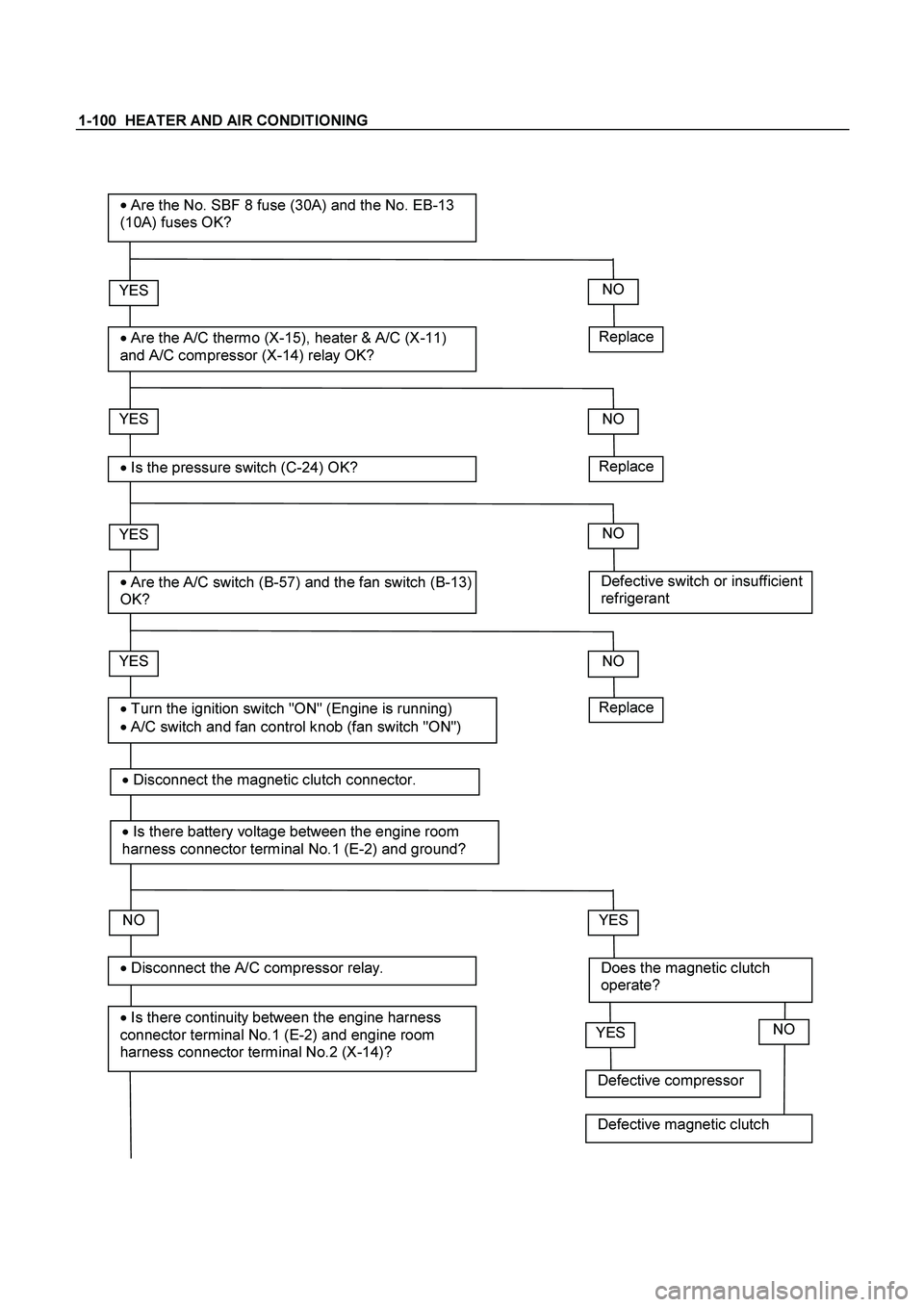
1-100 HEATER AND AIR CONDITIONING
Replace
YES
�
Are the A/C thermo (X-15), heater & A/C (X-11)
and A/C compressor (X-14) relay OK?
�
Are the No. SBF 8 fuse (30A) and the No. EB-13
(10A) fuses OK?
YES
�
Is the pressure switch (C-24) OK?
YES
�
Are the A/C switch (B-57) and the fan switch (B-13)
OK?
NO
YES
�
Is there continuity between the engine harness
connector terminal No.1 (E-2) and engine room
harness connector terminal No.2 (X-14)?
� Disconnect the A/C compressor relay.
�
Turn the ignition switch "ON" (Engine is running)
�
A/C switch and fan control knob (fan switch "ON")
NO
Replace
NO
Defective switch or insufficient
refrigerant
NO
NO
Does the magnetic clutch
operate?
YES
Replace
�
Disconnect the magnetic clutch connector.
� Is there battery voltage between the engine room
harness connector terminal No.1 (E-2) and ground?
Defective compressor
YESNO
Defective magnetic clutch
Page 3695 of 4264
 (V6 3.5L) 7A2-15
2. Indicator is flashing and the flash is 0.4 seconds
ON and 0.4 seconds OFF always when ignition is
on (engine cranked or not). This")
TRANSMISSION CONTROL SYSTEM (AW30 –40LE) (V6 3.5L) 7A2-15
2. Indicator is flashing and the flash is 0.4 seconds
ON and 0.4 seconds OFF always when ignition is
on (engine cranked or not). This means that there is
a malfunction. Go to DIAGNOSTIC CHECK
.
Abnormal
C07RY00042-1
3. Indicator is staying ON always when Ignition is ON.
1. This means that connection between the lamp
and the indicator control unit is shorted to
ground.
2. Verify if instrument panel terminal 2 o
f
connector B –23 is shorted to ground.
3. Verify if the indicator control unit connector C –
95 terminal 3 is shorted to ground.
4.
Verify that the instrument panel terminal 30 of
connector B –24 is connected to battery.
5. If problem solved: Go to CHECK TRANS
INDICATOR .
NO: Replace Transmission Control Module
(TCM).
4. Indicator is staying OFF with the ignition ON
(engine OFF).
1. This means that connection between the lamp
and the indicator control unit is shorted to
battery or opened.
2.
Verify if instrument panel terminal 2 of
connector B –23 is shorted to battery or open.
3. Verify if the indicator control unit connector C –
95 terminal 3 is shorted to battery or open.
4.
Verify that the instrument panel terminal 2of
connector B –23 is connected to battery. If not,
check the fuses and the connections (terminal
11 of connector H –6) voltage.