Page 1110 of 4264
8B-12 CRUISE CONTROL SYSTEM
CIRCUIT DIAGRAM
RTW48AXF003801
Page 1341 of 4264
ENGINE ELECTRICAL 6D – 3
GENERAL DESCRIPTION
GENERATOR STARTER MOTOR
066L300004065L300002
The basic charging system is the IC integral regulator charging system. The internal components are connected
electrically as shown in charging circuit diagram.
The generator features a solid state regulator that is mounted inside the generator. All regulator components are
enclosed into a solid mold, and this unit along with the brush holder assembly is attached to the slip ring end frame.
The generator voltage setting cannot be adjusted.
The starter motor circuit is composed of a 4-pole 4-brush type direct current series motor. The starter motor circuit
utilizes negative ground polarity.
Page 1342 of 4264
6D – 4 ENGINE ELECTRICAL
CHARGING CIRCUIT DIAGRAM
RTW46DSH005101
STARTING CIRCUIT DIAGRAM
RTW46DSH005501
Page 1371 of 4264
ENGINE ELECTRICAL 6D – 33
PRE-HEATING SYSTEM
INSPECTION AND REPAIR
Make the necessary adjustments, repairs, and part replacement if excessive wear of damage is discovered during
inspection.
VISUAL CHECK
Check the main fuses and glow indicator for damage.
Replace the part(s) if required.
GLOW RELAY
The glow relay is located in the relay box the engine
compartment.
825R300046
Use an ohmmeter to measure the resistance between
terminals No.2 and No.3.
If the measured value is outside the specified range, the
glow relay must be replaced.
Glow Relay Resistance Ohms
94 � 114
GLOW PLUG
LNW21KSH001401
Use a circuit tester to test the glow plugs for continuity.
Glow Plug Resistance (Reference) Ohms
Approximately 0.9
EGR SYSTEM 4JA1T (L)
Refer to 6F-9. (EGR system diagram)
Page 1373 of 4264

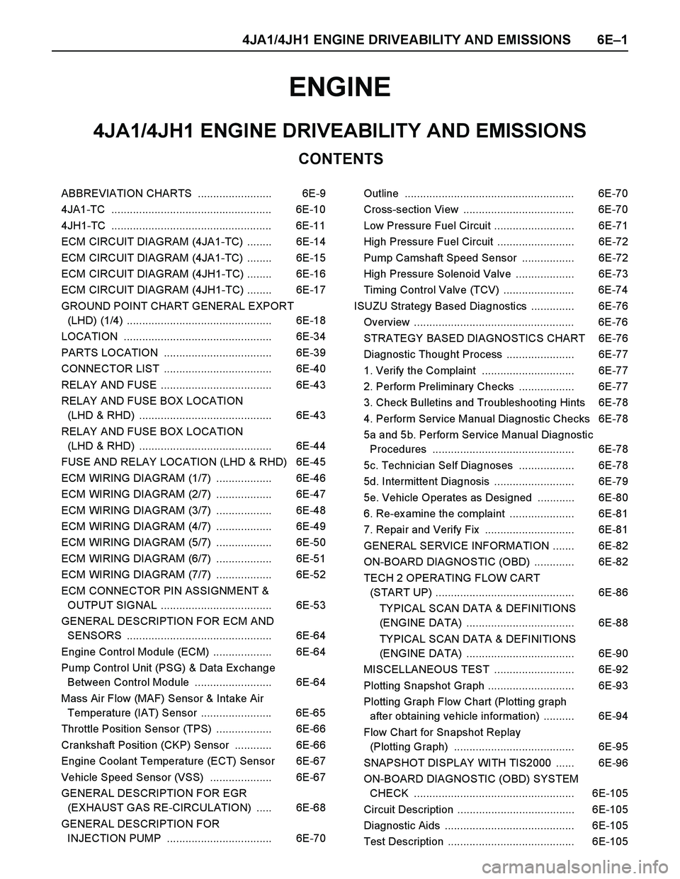
4JA1/4JH1 ENGINE DRIVEABILITY AND EMISSIONS 6E–1
ENGINE
CONTENTS
4JA1/4JH1 ENGINE DRIVEABILITY AND EMISSIONS
ABBREVIATION CHARTS ........................ 6E-9
4JA1-TC .................................................... 6E-10
4JH1-TC .................................................... 6E-11
ECM CIRCUIT DIAGRAM (4JA1-TC) ........ 6E-14
ECM CIRCUIT DIAGRAM (4JA1-TC) ........ 6E-15
ECM CIRCUIT DIAGRAM (4JH1-TC) ........ 6E-16
ECM CIRCUIT DIAGRAM (4JH1-TC) ........ 6E-17
GROUND POINT CHART GENERAL EXPORT
(LHD) (1/4) ............................................... 6E-18
LOCATION ................................................ 6E-34
PARTS LOCATION ................................... 6E-39
CONNECTOR LIST ................................... 6E-40
RELAY AND FUSE .................................... 6E-43
RELAY AND FUSE BOX LOCATION
(LHD & RHD) ........................................... 6E-43
RELAY AND FUSE BOX LOCATION
(LHD & RHD) ........................................... 6E-44
FUSE AND RELAY LOCATION (LHD & RHD) 6E-45
ECM WIRING DIAGRAM (1/7) .................. 6E-46
ECM WIRING DIAGRAM (2/7) .................. 6E-47
ECM WIRING DIAGRAM (3/7) .................. 6E-48
ECM WIRING DIAGRAM (4/7) .................. 6E-49
ECM WIRING DIAGRAM (5/7) .................. 6E-50
ECM WIRING DIAGRAM (6/7) .................. 6E-51
ECM WIRING DIAGRAM (7/7) .................. 6E-52
ECM CONNECTOR PIN ASSIGNMENT &
OUTPUT SIGNAL .................................... 6E-53
GENERAL DESCRIPTION FOR ECM AND
SENSORS ............................................... 6E-64
Engine Control Module (ECM) ................... 6E-64
Pump Control Unit (PSG) & Data Ex change
Between Control Module ......................... 6E-64
Mass Air Flow (MAF) Sensor & Intake Air
Temperature (IAT) Sensor ....................... 6E-65
Throttle Position Sensor (TPS) .................. 6E-66
Crankshaft Position (CKP) Sensor ............ 6E-66
Engine Coolant Temperature (ECT) Sensor 6E-67
Vehicle Speed Sensor (VSS) .................... 6E-67
GENERAL DESCRIPTION FOR EGR
(EXHAUST GAS RE-CIRCULATION) ..... 6E-68
GENERAL DESCRIPTION FOR
INJECTION PUMP .................................. 6E-70Outline ....................................................... 6E-70
Cross-section View .................................... 6E-70
Low Pressure Fuel Circuit .......................... 6E-71
High Pressure Fuel Circuit ......................... 6E-72
Pump Camshaft Speed Sensor ................. 6E-72
High Pressure Solenoid Valve ................... 6E-73
Timing Control Valve (TCV) ....................... 6E-74
ISUZU Strategy Based Diagnostics .............. 6E-76
Overview .................................................... 6E-76
STRATEGY BASED DIAGNOSTICS CHART 6E-76
Diagnostic Thought Process ...................... 6E-77
1. Verify the Complaint .............................. 6E-77
2. Perform Preliminary Checks .................. 6E-77
3. Check Bulletins and Troubleshooting Hints 6E-78
4. Perform Service Manual Diagnostic Checks 6E-78
5a and 5b. Perform Service Manual Diagnostic
Procedures .............................................. 6E-78
5c. Technician Self Diagnoses .................. 6E-78
5d. Intermittent Diagnosis .......................... 6E-79
5e. Vehicle Operates as Designed ............ 6E-80
6. Re-examine the complaint ..................... 6E-81
7. Repair and Verify Fix ............................. 6E-81
GENERAL SERVICE INFORMATION ....... 6E-82
ON-BOARD DIAGNOSTIC (OBD) ............. 6E-82
TECH 2 OPERATING FLOW CART
(START UP) ............................................. 6E-86
TYPICAL SCAN DATA & DEFINITIONS
(ENGINE DATA) ................................... 6E-88
TYPICAL SCAN DATA & DEFINITIONS
(ENGINE DATA) ................................... 6E-90
MISCELLANEOUS TEST .......................... 6E-92
Plotting Snapshot Graph ............................ 6E-93
Plotting Graph Flow Chart (Plotting graph
after obtaining vehicle information) .......... 6E-94
Flow Chart for Snapshot Replay
(Plotting Graph) ....................................... 6E-95
SNAPSHOT DISPLAY WITH TIS2000 ...... 6E-96
ON-BOARD DIAGNOSTIC (OBD) SYSTEM
CHECK .................................................... 6E-105
Circuit Description ...................................... 6E-105
Diagnostic Aids .......................................... 6E-105
Test Description ......................................... 6E-105
Page 1386 of 4264
6E–14 4JA1/4JH1 ENGINE DRIVEABILITY AND EMISSIONS
ECM CIRCUIT DIAGRAM (4JA1-TC)
Page 1387 of 4264
4JA1/4JH1 ENGINE DRIVEABILITY AND EMISSIONS 6E–15
ECM CIRCUIT DIAGRAM (4JA1-TC)
Page 1388 of 4264
6E–16 4JA1/4JH1 ENGINE DRIVEABILITY AND EMISSIONS
ECM CIRCUIT DIAGRAM (4JH1-TC)