Page 3959 of 4264

� The multi-plate brake is composed of drive plates and driven plates. By applying the oil pressure onto")
CONSTRUCTION AND FUNCTION 7A1-13
2-4 Brake and Low & Reverse Brake (Multi-Plate Brake)
� The multi-plate brake is composed of drive plates and driven plates. By applying the oil pressure onto
the end surface of the plates, the clutch is engaged or disengaged. The oil pressure is adjusted with the
control valve according to the signal from the TCM.
� All brakes use dish plates to prevent uncontrolled operation of the clutches when engaged, causing a
shock.
� The solenoid in the control valve is driven based on the speed change signal from TCM and moves the
shift valve, thereby engaging the drive plate and driven plate through the piston of each clutch.
� Resultantly, rotation of each element of the planetary gear unit is fixed.
� When the oil pressure is removed, the piston returns to the original position by the force of the return
spring.
Figure 19. Construction of 2-4 Brake
Figure 20. Construction of Low & Reverse Brake
Low One-way Clutch
� The low one-way clutch employs the sprag which locks the counterclockwise rotation of the front planetary
carrier and rear internal gear.
� The one-way clutch outer race is fitted with the low clutch drum and the inner race with the transmission
case.
� The outer race rotates freely clockwise but, when it attempts to rotate counterclockwise, the sprag
functions to lock the outer race.
� When the vehicle is traveling in 1st gear in the D, 3 or 2range, the low one-way clutch locks the rear
internal gear via the low clutch. It is left free in the 2nd, 3rd or 4th gear position.
Figure 21. Construction of Low One-way Clutch
Page 3960 of 4264
7A1-14 CONSTRUCTION AND FUNCTION
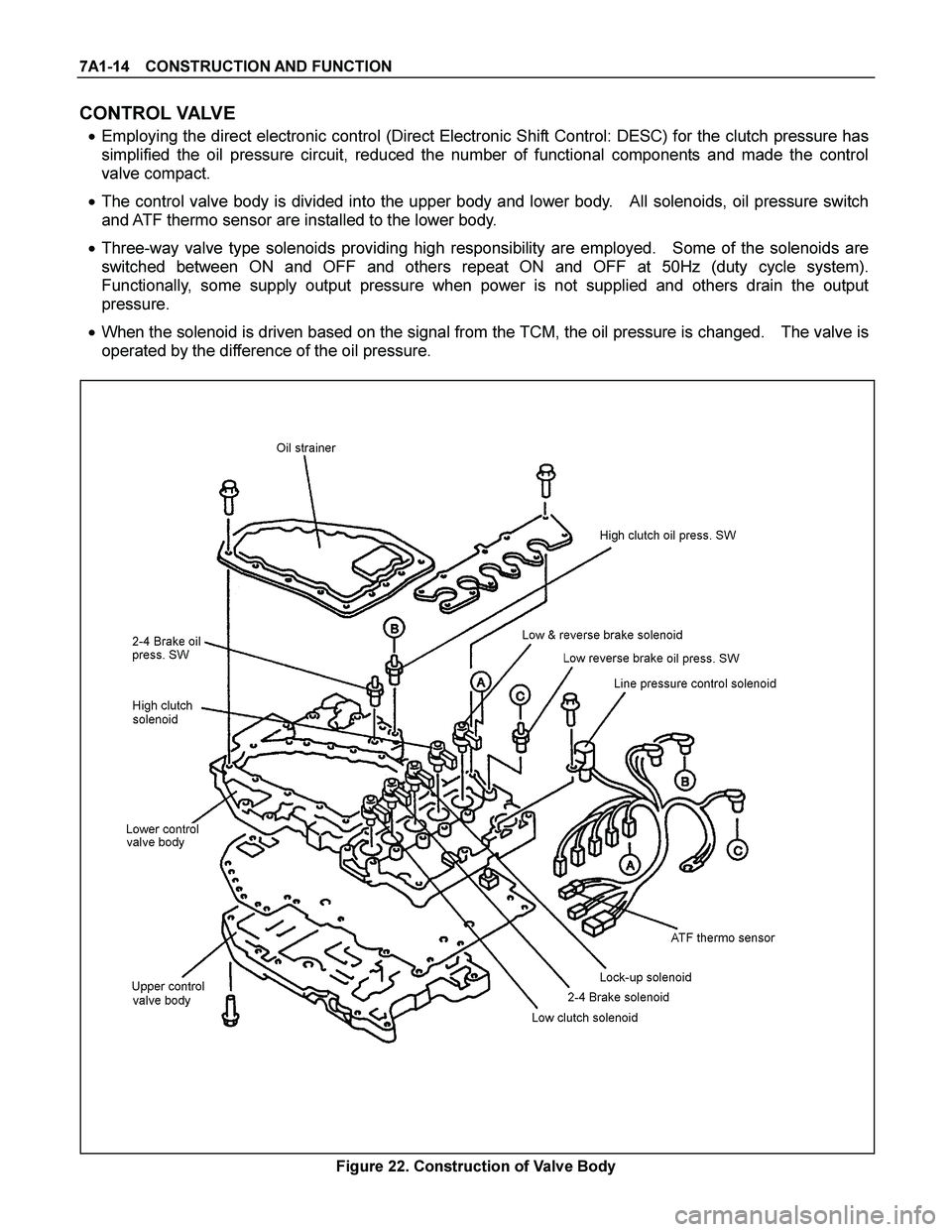
CONTROL VALVE
� Employing the direct electronic control (Direct Electronic Shift Control: DESC) for the clutch pressure has
simplified the oil pressure circuit, reduced the number of functional components and made the control
valve compact.
� The control valve body is divided into the upper body and lower body. All solenoids, oil pressure switch
and ATF thermo sensor are installed to the lower body.
� Three-way valve type solenoids providing high responsibility are employed. Some of the solenoids are
switched between ON and OFF and others repeat ON and OFF at 50Hz (duty cycle system).
Functionally, some supply output pressure when power is not supplied and others drain the output
pressure.
� When the solenoid is driven based on the signal from the TCM, the oil pressure is changed. The valve is
operated by the difference of the oil pressure.
Figure 22. Construction of Valve Body
Page 3961 of 4264

CONSTRUCTION AND FUNCTION 7A1-15
Line Pressure Solenoid
� The line pressure solenoid is turned ON or OFF according to the signal from the TCM. It switches the
line pressure between high and low pressure.
� While no power is supplied, the solenoid supplies high pressure.
Shift Solenoid
� The shift solenoid is of the duty cycle type which are turned ON or OFF at 50Hz. The ratio of the ON and
OFF time can be freely controlled in the range of 0 - 100%.
� While no power is supplied, the solenoid supplies output pressure.
� The low clutch solenoid adjusts the low clutch pressure, the high clutch solenoid the high clutch pressure,
the 2-4 brake solenoid the 2-4 brake pressure and the low & reverse brake solenoid the low & reverse
brake pressure respectively.
Lock-up Solenoid
� The lock-up solenoid is of the duty cycle type which is turned ON or OFF at 50Hz. The ratio of ON and
OFF time can be freely controlled in the range of 0-100%.
� While no power is supplied, the solenoid drains the output pressure.
Figure 23. Shift Solenoid Figure 24. Lock-up Solenoid
Figure 25. Location of Solenoid
Page 3962 of 4264

7A1-16 CONSTRUCTION AND FUNCTION
Control Valve Fail-safe Function
� To prevent interlocking due to engagement of more than three clutches and brakes at the same time, the
2-4 brake fail-safe valve A and B, and the low & reverse brake fail-safe valve A and B are provided.
� When oil pressure is generated in the high clutch and the low clutch, the 2-4 brake solenoid is turned ON
to drain the oil pressure applied to the 2-4 brake.
� When oil pressure is generated in the high clutch or 2-4 brake, the low & reverse brake solenoid is turned
ON to drain the oil pressure applied to the low & reverse brake.
Oil Pressure Switch
� The oil pressure switch detects the oil pressure supply condition to the clutch and brake and sends the
detection result to the TCM.
� The oil pressure switch is turned ON when the oil pressure reaches the switch working pressure and
turned OFF when the pressure decreases below the specified value.
� The high clutch oil pressure switch detects the high clutch oil pressure, 2-4 brake oil pressure switch the
2-4 brake oil pressure, and the low & reverse brake oil pressure switch the low & reverse brake oil
pressure respectively.
Figure 27. Oil Pressure Switch Figure 28. Location of Oil Pressure Switch
Page 3963 of 4264

CONSTRUCTION AND FUNCTION 7A1-17
ATF Thermo Sensor
� The ATF thermo sensor detects the ATF temperature in the oil pan and sends signal to the TCM.
� The ATF thermo sensor is of the thermister type that the resistance value changes according to the ATF
oil temperature.
� The lower is the ATF temperature, the larger is the resistance, and vice versa.
� When the ATF temperature exceeds 145�C, the TCM lights up the ATF temperature warning lamp in the
meter. When the ATF temperature decreases below 128�C, the ATF temperature warning lamp goes out.
� The ATF thermo sensor is installed to the lower control valve body and integrated with the harness
assembly.
10.0 100.0 1,000.0 10,000.0 100,000.0
-30 -20 -10 0 10 20 30 40 50 60 70 80 90 100 110 120 130 140 150 160
A TF Temperature (°C)
Resistance (�
)
Figure 29. Characteristic of Thermo Sensor
Figure 30. Location of Thermo Sensor
ATF Temperature
(deg. C) Resistance (Ohm)
(Approximately) ATF Temperature
(deg. C) Resistance (Ohm)
(Approximately)
-30 29,614 100 190
-20 16,705 110 149
-10 9,842 120 118
0 6,028 128 98
20 2,500 130 94
40 1,160 135 84
50 819 140 76
60 591 145 68
80 324 150 62
Page 3964 of 4264
7A1-18 CONSTRUCTION AND FUNCTION
Terminal Assembly
Pin No. Connected to Connected TCMPin No.
6 Line Pressure Solenoid B23
12 Low & Reverse Brake Oil Pressure Switch B12
5 Low & Reverse Brake Duty Solenoid B6
11 Ground Return B22
4 Lock-up Duty Solenoid B17
10 High Clutch Duty Solenoid B8
3 Low Clutch Duty Solenoid B9
9 2-4 Brake Duty Solenoid B7
2 Oil Thermo Sensor B4
8 Oil Thermo Sensor Ground B14
1 High Clutch Oil Pressure Switch B20
7 2-4 Brake Oil Pressure Switch B1
123456
891011127
Terminal Assembly Inhibitor Switch
Figure 31. Pin Assignment Figure 32. Location of Terminal Assembly
Page 3967 of 4264
CONSTRUCTION AND FUNCTION 7A1-21
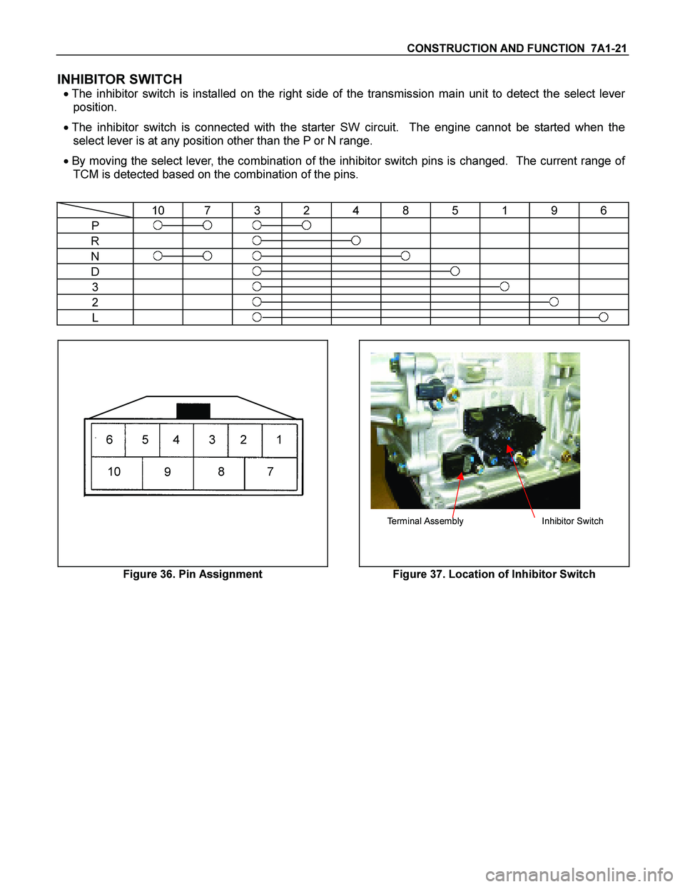
INHIBITOR SWITCH
� The inhibitor switch is installed on the right side of the transmission main unit to detect the select lever
position.
� The inhibitor switch is connected with the starter SW circuit. The engine cannot be started when the
select lever is at any position other than the P or N range.
� By moving the select lever, the combination of the inhibitor switch pins is changed. The current range of
TCM is detected based on the combination of the pins.
10 7 3 2 4 8 5 1 9 6
P
R
N
D
3
2
L
6345
10987
21
Terminal Assembly Inhibitor Switch
Figure 36. Pin Assignment Figure 37. Location of Inhibitor Switch
Page 3968 of 4264
7A1-22 CONSTRUCTION AND FUNCTION
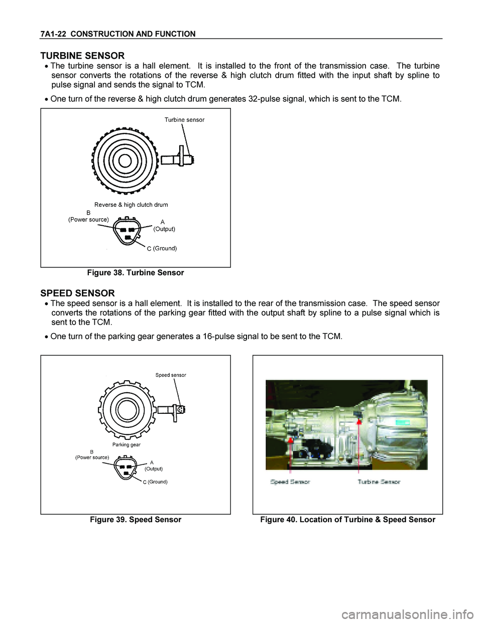
TURBINE SENSOR
� The turbine sensor is a hall element. It is installed to the front of the transmission case. The turbine
sensor converts the rotations of the reverse & high clutch drum fitted with the input shaft by spline to
pulse signal and sends the signal to TCM.
� One turn of the reverse & high clutch drum generates 32-pulse signal, which is sent to the TCM.
Figure 38. Turbine Sensor
SPEED SENSOR
� The speed sensor is a hall element. It is installed to the rear of the transmission case. The speed sensor
converts the rotations of the parking gear fitted with the output shaft by spline to a pulse signal which is
sent to the TCM.
� One turn of the parking gear generates a 16-pulse signal to be sent to the TCM.
Figure 39. Speed Sensor Figure 40. Location of Turbine & Speed Sensor