Page 683 of 4264
ELECTRICAL-BODY AND CHASSIS 8A-25
Light Name Rated Power
V-W Number of
Bulbs Lens
Color Remarks
W/O Tacho 5Illumination light 14-2
W/ Tacho 7White
Turn Signal 14-1.12 2 Green
High Beam 14-1.12 1 Blue
Low Fuel 14-1.12 1 Amber
A/T Oil Temp 14-1.12 1 Red
Brake system 14-1.12 1 Red
4WD 14-1.12 1 Green
Seat belt 14-1.12 1 Red
Oil pressure 14-1.12 1 Red
ABS 14-1.12 1 Amber
SEDIMENTER 14-1.12 1 Red
AIR BAG 14-1.12 1 Red
Brake 14-1.12 1 Red
Charge 14-1.12 1 Red
Check Trans 14-1.12 1 Red
Check 4WD 14-1.12 1 Red
Power drive 14-1.12 1 Amber
3rd start 14-1.12 1 Green
4L 14-1.12 1 Green
Cruise Set 14-1.12 1 Green
Check Engine 14-1.12 1 Amber
Front Fog 14-1.12 1 Green
Rear foglight 14-1. 12 1 Amber
Glow 14-1.12 1 Amber
P LED 1 Green
R LED 1 Green
N LED 1 Green
D LED 1 Green
3 LED 1 Green
2 LED 1 Green
Indicator/
Warning
light
A/T shift
indicator
L LED 1 Green
Page 819 of 4264
ELECTRICAL-BODY AND CHASSIS 8A-161
HAZARD WARNING FLASHER, TURN SIGNAL LIGHT, BACK UP
LIGHT, HORN AND STOP LIGHT
PARTS LOCATION (RHD)
RTW48AXF016601 & RTW48AXF016701
Page 826 of 4264
8A-168 ELECTRICAL-BODY AND CHASSIS
TURN SIGNAL LIGHT AND HAZARD WARNING LIGHT
1. Turn signal light does not light on both sides (RH and LH)
Checkpoint Trouble Cause Countermeasure
Replace the flasher unit
Flasher unit malfunction
NG
Repair or replace the
combination switch
Turn signal switch continuity
between connector
5
B-60 - 6 B-60 and
5
B-60 - 7 B-60 when
turn signal switch operates
Short circuit between
connector 3
B-61 - 1 B-61
when turn signal switch
operates with starter switch
in “ON” position (Turn
signal light should be ON)
Poor switch point contact or
faulty switch
NG OK
Reinstall or replace fuse No.
EB-16 (10A)
Fuse No. EB-16 (10A, Fuse
box)
Poor fuse contact or blown
fuse
NG
OK OK
Repair open circuit or
connector contact
Continuity between
connector 2
B-61 -ground
(Should be continuity)
Open circuit or poor connector
contact
NG
Page 827 of 4264

ELECTRICAL-BODY AND CHASSIS 8A-169
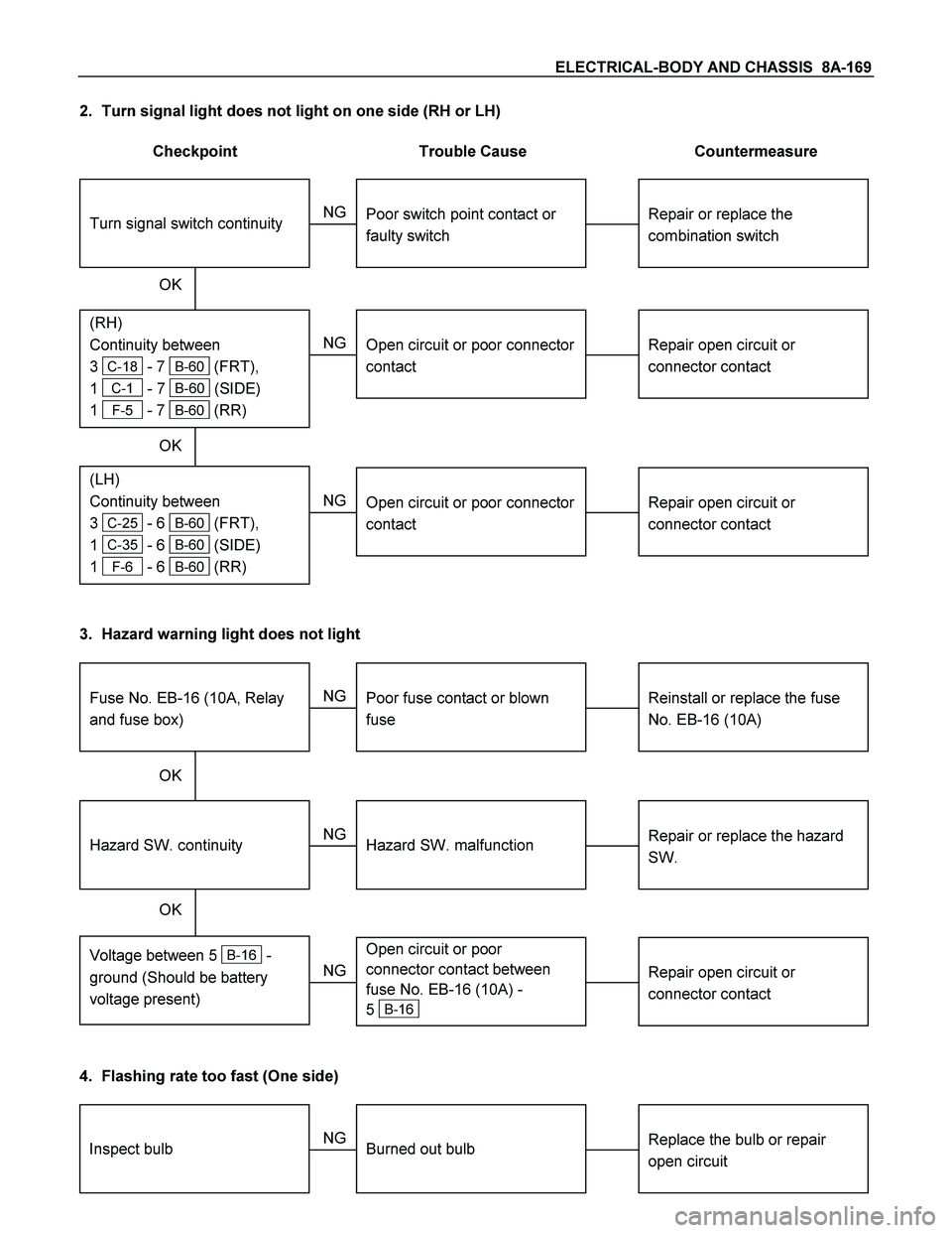
2. Turn signal light does not light on one side (RH or LH)
Checkpoint Trouble Cause Countermeasure
Repair open circuit or
connector contact
Open circuit or poor connector
contact
NG
(LH)
Continuity between
3
C-25 - 6 B-60 (FRT),
1
C-35 - 6 B-60 (SIDE)
1
F-6 - 6 B-60 (RR)
(RH)
Continuity between
3
C-18 - 7 B-60 (FRT),
1
C-1 - 7 B-60 (SIDE)
1
F-5 - 7 B-60 (RR)
Repair or replace the
combination switch
Turn signal switch continuity
Poor switch point contact or
faulty switch
NG
OK OK
Repair open circuit or
connector contact
Open circuit or poor connector
contact
NG
3. Hazard warning light does not light
Repair or replace the hazard
SW.
Hazard SW. malfunction
NG
Voltage between 5 B-16 -
ground (Should be battery
voltage present)
Hazard SW. continuity
Reinstall or replace the fuse
No. EB-16 (10A)
Fuse No. EB-16 (10A, Relay
and fuse box)
Poor fuse contact or blown
fuse
NG
OK OK
Repair open circuit or
connector contact
Open circuit or poor
connector contact between
fuse No. EB-16 (10A) -
5
B-16 NG
4. Flashing rate too fast (One side)
Replace the bulb or repair
open circuitInspect bulbBurned out bulb NG
Page 835 of 4264

ELECTRICAL-BODY AND CHASSIS 8A-177
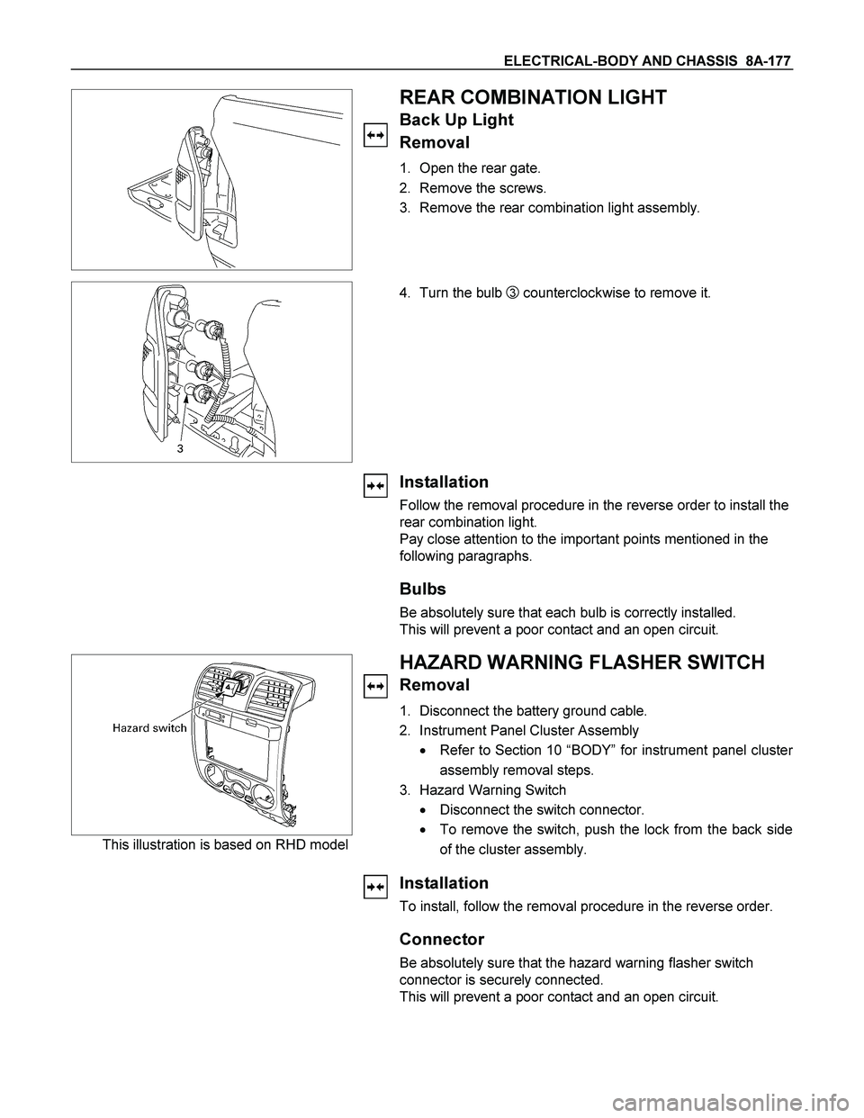
REAR COMBINATION LIGHT
Back Up Light
Removal
1. Open the rear gate.
2. Remove the screws.
3. Remove the rear combination light assembly.
4. Turn the bulb
3 counterclockwise to remove it.
Installation
Follow the removal procedure in the reverse order to install the
rear combination light.
Pay close attention to the important points mentioned in the
following paragraphs.
Bulbs
Be absolutely sure that each bulb is correctly installed.
This will prevent a poor contact and an open circuit.
This illustration is based on RHD model
HAZARD WARNING FLASHER SWITCH
Removal
1. Disconnect the battery ground cable.
2. Instrument Panel Cluster Assembly
� Refer to Section 10 “BODY” for instrument panel cluste
r
assembly removal steps.
3. Hazard Warning Switch
� Disconnect the switch connector.
� To remove the switch, push the lock from the back side
of the cluster assembly.
Installation
To install, follow the removal procedure in the reverse order.
Connector
Be absolutely sure that the hazard warning flasher switch
connector is securely connected.
This will prevent a poor contact and an open circuit.
Page 838 of 4264
8A-180 ELECTRICAL-BODY AND CHASSIS
3. Push the SRS air bag area1 and area2. At that time confirm
the audible noise of each stud.
4. Enable the SRS (Refer to “Enabling the SRS”in this
section).
INSPECTION AND REPAIR
Switch side Harness side
B-60 B-60
TURN SIGNAL SWITCH
Lighting Switch Connections
Terminal No.
SW position 5 6 7
Left
Neutral
Right
Turning
direction
Switch side
B-16
HAZARD WARNING FLASHER SWITCH
Hazard Warning Flasher Switch Connections
Terminal
No.
SW position
4
6
5
3
2
1
7
8
ON
OFF
Page 839 of 4264
ELECTRICAL-BODY AND CHASSIS 8A-181
DOME LIGHT, SPOT LIGHT AND WARNING BUZZER
PARTS LOCATION (RHD)
RTW48AXF017001 & RTW48AXF017101
Page 852 of 4264

8A-194 ELECTRICAL-BODY AND CHASSIS
Installation
Follow the removal procedure in the reverse order to install the
spot light.
Pay close attention to the important points mentioned in the
following paragraphs.
Connector
Be absolutely sure that the spot light connector is securely
connected.
This will prevent a poor contact and an open circuit.
Bulb
Be absolutely sure that the spot light bulb is correctly installed.
This will prevent a poor contact and an open circuit.
RTW48ASH000801
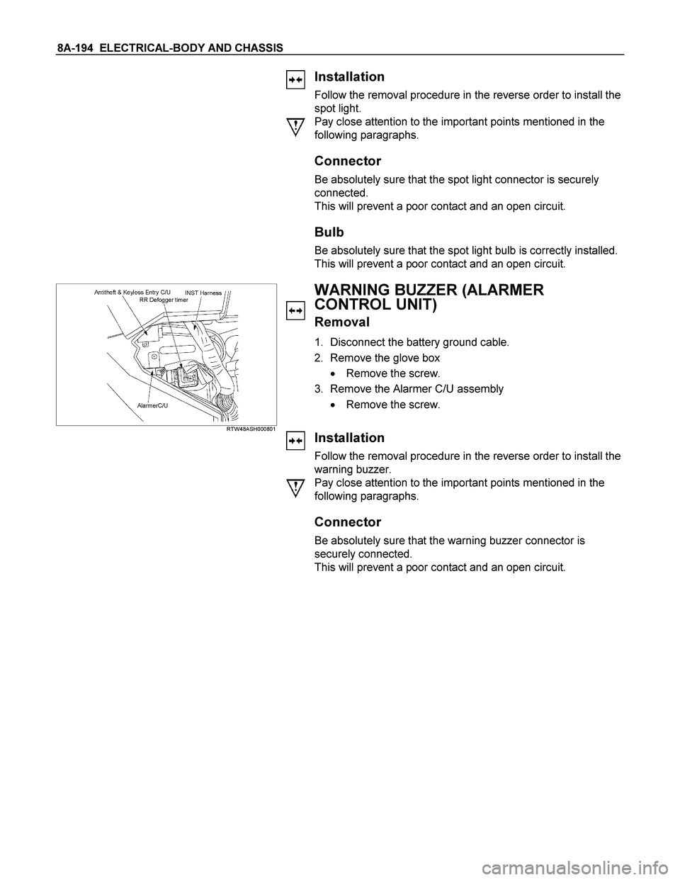
WARNING BUZZER (ALARMER
CONTROL UNIT)
Removal
1. Disconnect the battery ground cable.
2. Remove the glove box
� Remove the screw.
3. Remove the Alarmer C/U assembly
� Remove the screw.
Installation
Follow the removal procedure in the reverse order to install the
warning buzzer.
Pay close attention to the important points mentioned in the
following paragraphs.
Connector
Be absolutely sure that the warning buzzer connector is
securely connected.
This will prevent a poor contact and an open circuit.