Page 3449 of 4264

POWER-ASSISTED STEERING SYSTEM 3B-19
Reassembly
1. Install oil seal to front housing. Be sure to discard
used oil seal, and always use new parts fo
r
installation.
CAUTION: When installing the oil seal, be careful
not to damage the oil seal contacting surface of the
housing.
2. Install shaft assembly.
3. Install the vanes to roter with curved face in contac
t
with the inner wall of cam.
442RS005
4. Install roter and vanes to cam.
5. Install pin to front housing.
6. Install two new O-rings to front housing. Be sure to
discard used O-ring.
7. Install side plate.
CAUTION: When installing side plate, be careful not
to damage its inner surface. Damaged side plate
may cause poor pump performance, pump seizure
or oil leakage.
8. Install pump cartridge assembly to front housing.
9. Install snap ring to shaft end.
10. Install rear housing with a new O-ring. Be sure to
discard used O-ring. Then install bolt and tighten it
to specified torque.
Torque: 22-26 N�
�� �m (2.2-2.7kg�
�� �m/16-20 lb ft)
11. Install suction pipe with a new O-ring. Be sure to
discard used O-ring. Then install bolt and tighten it
to specified torque.
Torque: 7.8-12 N�
�� �m (0.8-1.2kg�
�� �m/69-104 lb in)
12. Install relief valve and spring.
13. Install connector with a new O-ring. Be sure to
discard used O-ring. Tighten the connector to
specified torque.
Torque: 49-69 N�
�� �m (5.0-7.0kg�
�� �m/36-51 lb ft)
Main Data and Specifications
General Specifications
Oil pump Type Vane
Operating fluid
ATF DEXRON®�
III
Page 3455 of 4264
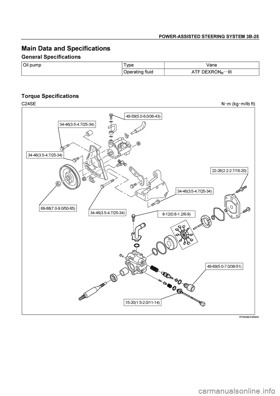
POWER-ASSISTED STEERING SYSTEM 3B-25
Main Data and Specifications
General Specifications
Oil pump Type Vane
Operating fluid
ATF DEXRON®�
III
Torque Specifications
C24SE N�
m (kg�
m/Ib ft)
RTW43BLF000401
Page 3460 of 4264
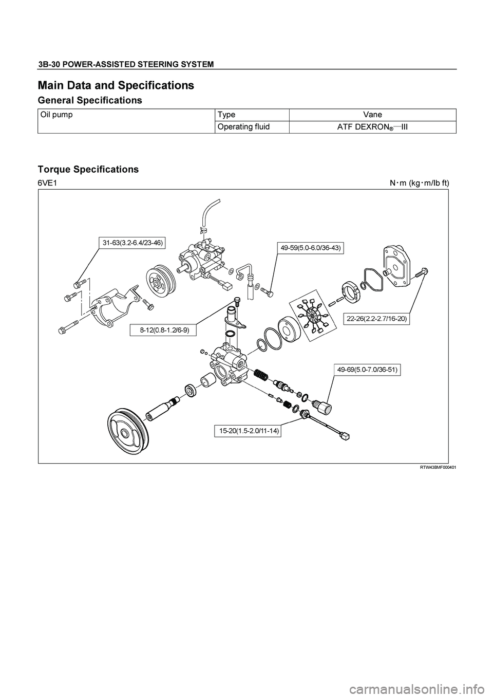
3B-30 POWER-ASSISTED STEERING SYSTEM
Main Data and Specifications
General Specifications
Oil pump Type Vane
Operating fluid
ATF DEXRON®�
III
Torque Specifications
6VE1 N�
m (kg�
m/Ib ft)
RTW43BMF000401
Page 3470 of 4264

3B-40 POWER-ASSISTED STEERING SYSTEM
430RX005-X
14. Remove steering column cover.
15. Disconnect the wiring harness connectors located
under the steering column then remove combination
switch and SRS coil assembly.
Installation
1. Align the setting marks made when removing then
install steering wheel.
Refer to the adjustment method in case a mark is
not attached in this section.
NOTE: Confirm SRS and Horn harness connector is
fixed by the steering wheel.
RTW33BSH000601
CAUTION: Never apply force to the steering wheel in
direction of the shaft by using a hammer or othe
r
impact tools in an attempt to remove the steering
wheel. The steering shaft is designed as an energy
absorbing unit.
2. Tighten the steering wheel fixing nut to the specified
torque.
Torque: 31 - 39 N�
�� �
m (3.2 – 4.0 kg�
�� �
m/23 - 29 lb ft)
3. Support the inflator module and carefully connect the
SRS connector and horn lead. (with SRS air bag)
060R300041
4. Connect the horn leads at center of wheel. (without
SRS air bag)
NOTE: Horn leads is letting a bracket top pass.
(Plastic type steering wheel only)
RTW43BSH000301
Page 3494 of 4264
 MODEL
Front suspension Type Independent wishbone arms, coil spring
with stabilizer bar.
Coil spring")
3C-2 FRONT SUSPENSION
MAIN DATA AND SPECIFICATIONS
4�
�� �2 (EXCEPT HIGH RIDE SUSPENSION) MODEL
Front suspension Type Independent wishbone arms, coil spring
with stabilizer bar.
Coil spring Spring Rate 4JH1-TC / 4JA1-TC / 4JA1-L (ENGINE); 9.62 kg/mm
(94.3 N/mm)
C24SE (ENGINE); 7.94 kg/mm (77.9 N/mm)
Type Gas-sealed. Hydraulic, double acting
Stroke 116.5 mm (4.59 in)
Compressed length 284.0 mm (11.18 in)
Front shock absorber
Extended length 400.5 mm (15.77 in)
Stabilizer bar Diameter 25.0 mm (0.98 in)
4�
�� �2 (HIGH RIDE SUSPENSION) MODEL
Front suspension Type Independent wishbone arms, torsion bar spring
with stabilizer bar.
Length 1142 mm (44.96 in) Torsion bar spring
Diameter 29.0 mm (1.14 in)
Type Gas-sealed. Hydraulic, double acting
Stroke 121.0 mm (4.76 in)
Compressed length 257.0 mm (10.12 in)
Front shock absorber
Extended length 378.0 mm (14.88 in)
Stabilizer bar Diameter 26.0 mm (1.02 in)
4�
�� �4 MODEL
Front suspension Type Independent wishbone arms, torsion bar spring
with stabilizer bar.
Length 1142 mm (44.96 in) Torsion bar spring
Diameter 29.0 mm (1.14 in)
Type Gas-sealed. Hydraulic, double acting
Stroke 121.0 mm (4.76 in)
Compressed length 257.0 mm (10.12 in)
Front shock absorber
Extended length 378.0 mm (14.88 in)
Stabilizer bar Diameter 26.0 mm (1.02 in)
Page 3499 of 4264
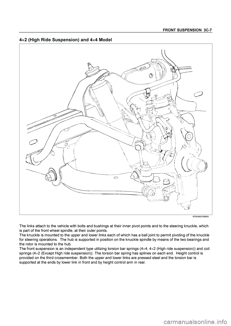
FRONT SUSPENSION 3C-7
4
�
�� �2 (High Ride Suspension) and 4
�
�� �4 Model
RTW340LF000801
The links attach to the vehicle with bolts and bushings at their inner pivot points and to the steering knuckle, which
is part of the front wheel spindle, at their outer points.
The knuckle is mounted to the upper and lower links each of which has a ball joint to permit pivoting of the knuckle
for steering operations. The hub is supported in position on the knuckle spindle by means of the two bearings and
the rotor is mounted to the hub.
The front suspension is an independent type utilizing torsion bar springs (4�
4, 4�
2 (High ride suspension)) and coil
springs (4�
2 (Except High ride suspension)). The torsion bar spring has splines on each end. Height control is
provided on the third crossmember. Both the upper and lower links are pressed steel and the torsion bar is
supported at the ends by lower link in front and by height control arm in rear.
Page 3531 of 4264

FRONT SUSPENSION 3C-39
Inspection and Repair
Make necessary correction or parts replacement if
wear, damage, corrosion or any other abnormal
condition are found through inspection.
Check the following parts:
�
Knuckle
�
Knuckle arm
� Thrust washer (4�4 Model Only)
Installation
1. Apply appropriate amount of multipurpose type
grease to the new bearing (Approx. 5 g) and
install needle bearing by using installer 5-8840-
2128-0 and grip 5-8840-0007-0. (4�
4 Model Only)
(4�4 Model Only)
901RW275
2. Apply multipurpose type grease to the thrust
washer, and install washer with chamfered side
facing knuckle. (4�4 Model Only)
3. Use a new oil seal, and apply multipurpose type
grease to the area surrounded by the lip (approx. 2
g). Then use installer 5-8840-2127-0 and grip 5-
8840-0007-0 to install oil seal. After fitting the oil
seal to the installer, drive it to the knuckle using a
hammer or bench press until the tool front face
contacts with the thrust washer. (4�
4 Model Only)
(4�4 Model Only)
901RW274
4. Install knuckle assembly.
5. Install upper ball joint and tighten the nut to the
specified torque, with just enough additional torque
to align cotter pin holes. Install new cotter pin (9).
Torque: 98 N�
�� �m (10.0kg�
�� �m/72 lb ft)
6. Install lower ball joint and tighten the nut to the
specified torque, with just enough additional torque
to align cotter pin holes. Install new cotter pin (2).
Torque: 147 N
�
�� �m (15.0kg
�
�� �m/108 lb ft)
7. Install back plate.
8. Install speed sensor harness.
9. Install torsion bar, refer to Torsion Bar in this
section.
NOTE: Adjust the trim height. Refer to Front End
Alignment Inspection and Adjustment in Steering.
Page 3604 of 4264
7D-16 TRANSFER CASE
23.
Remove the retaining ring (spiral type) together with
the internal gear and the damper ring.
226R300004
24.
Remove the snap ring.
25.
Use a press to remove the front output shaft ball
bearings.
26.
Remove the oil pump wire snap ring from the rea
r
cover.
27.
Use a sliding hammer (5-8840-0084-0) and a needle
bearing replacer (5-8840-2788-0) to remove the
needle bearing from the front output shaft.
P1010023
Legend
(1) Dumper Ring
(2) Internal Gear
(3) Retaining Ring
 together with
the internal gear and the damper ring.
226R300004
24.
Remove the snap ring.
25.
Use a press")