Page 2907 of 3371
RSU-48
SERVICE DATA AND SPECIFICATIONS (SDS)
Revision: August 20072004 QX56
Wheelarch Height (Unladen*1 )EES0011Z
Unit: mm (in)
*1: Fuel, engine coolant and engine oil full. Spare tire, jack, hand tools and mats in designated positions.
*2: Verify the vehicle height using Consult-II memory register 1103 and set rear wheelarch height to 0 ± 10 mm (0 ± 0.39 in) as neces-
sary.Suspension type
Air leveling*
2
Applied model4x2 4x4
Front wheelarch height (Hf)913
(35.94)931
(36.65)
Rear wheelarch height (Hr)912
(35.91)932
(36.69)
LEIA0085E
Page 2925 of 3371

SC-4
BATTERY
Revision: August 20072004 QX56
BATTERYPFP:AYBGL
How to Handle BatteryEKS00795
CAUTION:
�If it becomes necessary to start the engine with a booster battery and jumper cables, use a 12-volt
booster battery.
�After connecting battery cables, ensure that they are tightly clamped to battery terminals for good
contact.
�Never add distilled water through the hole used to check specific gravity.
METHODS OF PREVENTING OVER-DISCHARGE
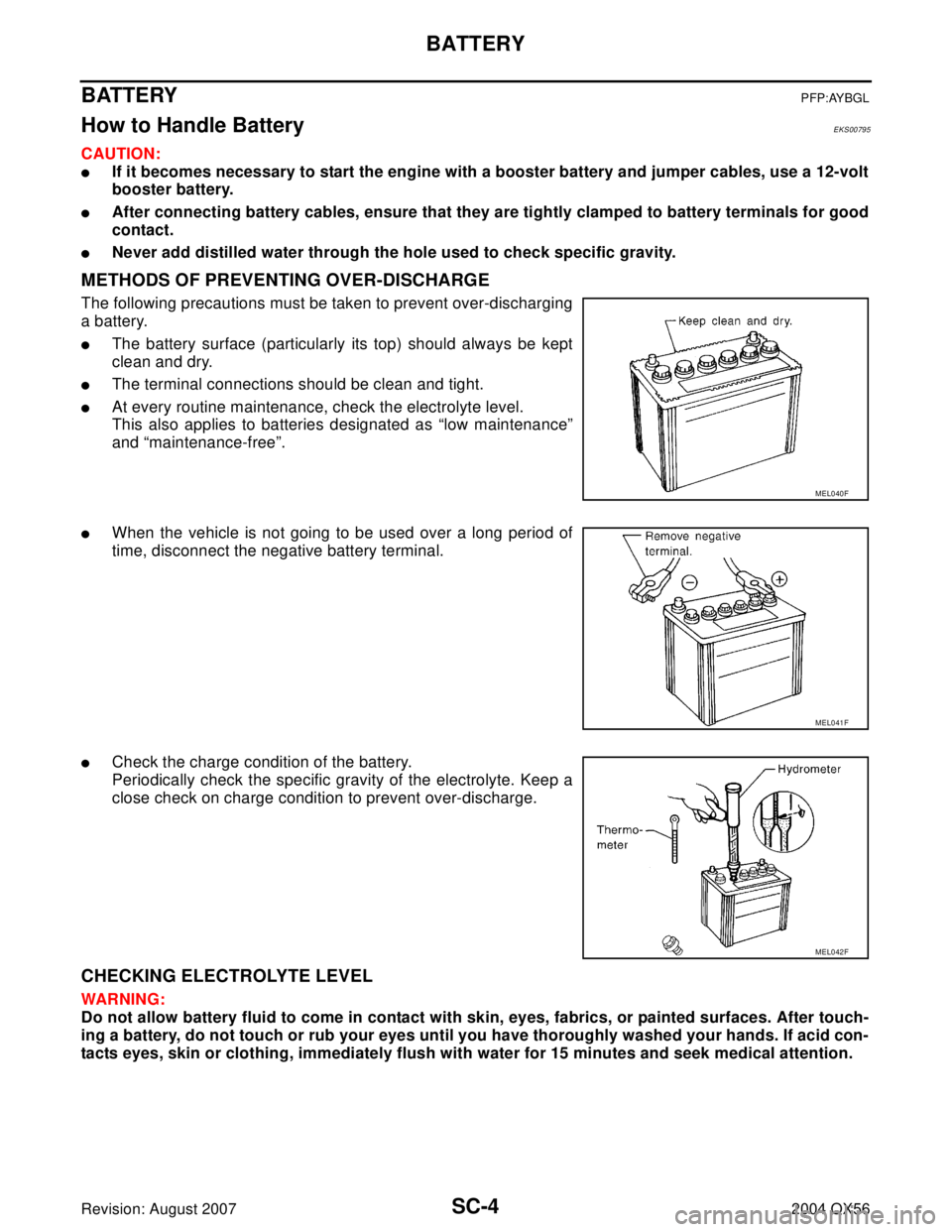
The following precautions must be taken to prevent over-discharging
a battery.
�The battery surface (particularly its top) should always be kept
clean and dry.
�The terminal connections should be clean and tight.
�At every routine maintenance, check the electrolyte level.
This also applies to batteries designated as “low maintenance”
and “maintenance-free”.
�When the vehicle is not going to be used over a long period of
time, disconnect the negative battery terminal.
�Check the charge condition of the battery.
Periodically check the specific gravity of the electrolyte. Keep a
close check on charge condition to prevent over-discharge.
CHECKING ELECTROLYTE LEVEL
WAR NIN G:
Do not allow battery fluid to come in contact with skin, eyes, fabrics, or painted surfaces. After touch-
ing a battery, do not touch or rub your eyes until you have thoroughly washed your hands. If acid con-
tacts eyes, skin or clothing, immediately flush with water for 15 minutes and seek medical attention.
MEL040F
MEL041F
MEL042F
Page 2931 of 3371

SC-10
STARTING SYSTEM
Revision: August 20072004 QX56
STARTING SYSTEMPFP:23300
System DescriptionEKS00798
Power is supplied at all times:
�through 40A fusible link (letter m , located in the fuse and fusible link box)
�to ignition switch terminal B.
With the ignition switch in the START position, power is supplied:
�from ignition switch terminal ST
�to IPDM E/R terminal 21.
With the ignition switch in the ON or START position, power is supplied to IPDM E/R (intelligent power distribu-
tion module engine room) CPU.
With the selector lever in the P or N position, power is supplied:
�through A/T assembly terminal 9
�to IPDM E/R terminal 48.
Ground is supplied at all times:
�to IPDM E/R terminals 38 and 59
�from body grounds E9, E15 and E24.
Then the starter relay is turned on.
The IPDM E/R is energized and power is supplied:
�from terminal 19 of the IPDM E/R
�to terminal 1 of the starter motor windings.
The starter motor plunger closes and provides a closed circuit between the battery and the starter motor. The
starter motor is grounded to the cylinder block. With power and ground supplied, the starter motor operates.
Page 2933 of 3371

SC-12
STARTING SYSTEM
Revision: August 20072004 QX56
Trouble Diagnoses with Battery/Starting/Charging System TesterEKS0079A
NOTE:
To ensure a complete and thorough diagnosis, the battery, starter and generator test segments must be done
as a set from start to finish.
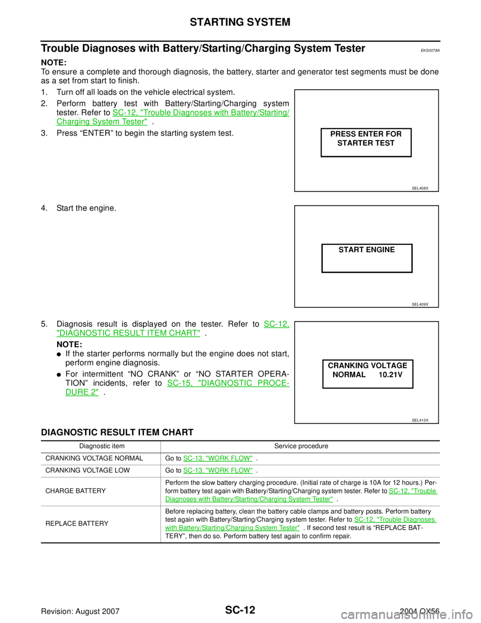
1. Turn off all loads on the vehicle electrical system.
2. Perform battery test with Battery/Starting/Charging system
tester. Refer to SC-12, "
Trouble Diagnoses with Battery/Starting/
Charging System Tester" .
3. Press “ENTER” to begin the starting system test.
4. Start the engine.
5. Diagnosis result is displayed on the tester. Refer to SC-12,
"DIAGNOSTIC RESULT ITEM CHART" .
NOTE:
�If the starter performs normally but the engine does not start,
perform engine diagnosis.
�For intermittent “NO CRANK” or “NO STARTER OPERA-
TION” incidents, refer to SC-15, "
DIAGNOSTIC PROCE-
DURE 2" .
DIAGNOSTIC RESULT ITEM CHART
SEL408X
SEL409X
SEL410X
Diagnostic item Service procedure
CRANKING VOLTAGE NORMAL Go to SC-13, "
WORK FLOW" .
CRANKING VOLTAGE LOW Go to SC-13, "
WORK FLOW" .
CHARGE BATTERYPerform the slow battery charging procedure. (Initial rate of charge is 10A for 12 hours.) Per-
form battery test again with Battery/Starting/Charging system tester. Refer to SC-12, "
Trouble
Diagnoses with Battery/Starting/Charging System Tester" .
REPLACE BATTERYBefore replacing battery, clean the battery cable clamps and battery posts. Perform battery
test again with Battery/Starting/Charging system tester. Refer to SC-12, "
Trouble Diagnoses
with Battery/Starting/Charging System Tester" . If second test result is “REPLACE BAT-
TERY”, then do so. Perform battery test again to confirm repair.
Page 2935 of 3371

SC-14
STARTING SYSTEM
Revision: August 20072004 QX56
DIAGNOSTIC PROCEDURE 1
Check Terminal "2" Circuit
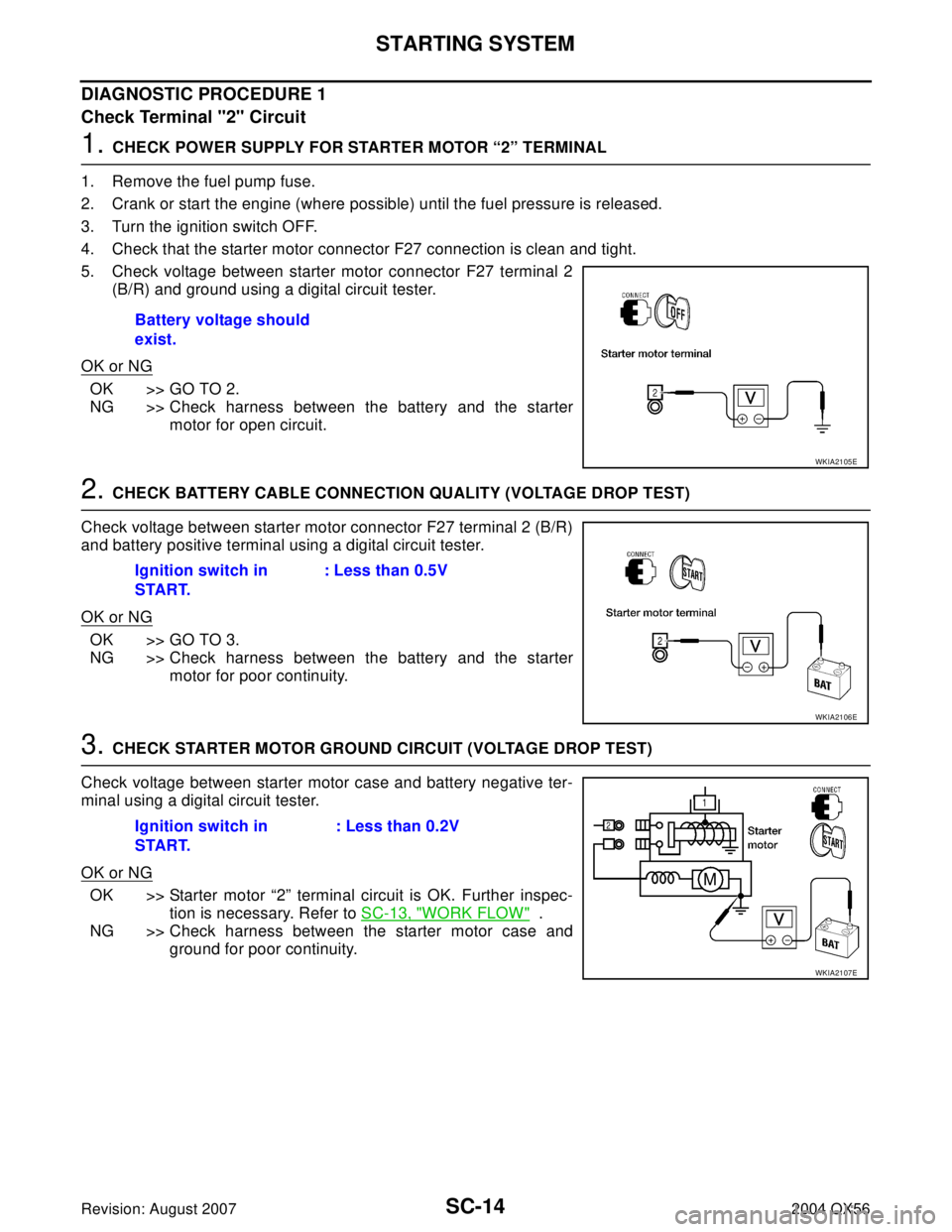
1. CHECK POWER SUPPLY FOR STARTER MOTOR “2” TERMINAL
1. Remove the fuel pump fuse.
2. Crank or start the engine (where possible) until the fuel pressure is released.
3. Turn the ignition switch OFF.
4. Check that the starter motor connector F27 connection is clean and tight.
5. Check voltage between starter motor connector F27 terminal 2
(B/R) and ground using a digital circuit tester.
OK or NG
OK >> GO TO 2.
NG >> Check harness between the battery and the starter
motor for open circuit.
2. CHECK BATTERY CABLE CONNECTION QUALITY (VOLTAGE DROP TEST)
Check voltage between starter motor connector F27 terminal 2 (B/R)
and battery positive terminal using a digital circuit tester.
OK or NG
OK >> GO TO 3.
NG >> Check harness between the battery and the starter
motor for poor continuity.
3. CHECK STARTER MOTOR GROUND CIRCUIT (VOLTAGE DROP TEST)
Check voltage between starter motor case and battery negative ter-
minal using a digital circuit tester.
OK or NG
OK >> Starter motor “2” terminal circuit is OK. Further inspec-
tion is necessary. Refer to SC-13, "
WORK FLOW" .
NG >> Check harness between the starter motor case and
ground for poor continuity. Battery voltage should
exist.
WKIA2105E
Ignition switch in
START.: Less than 0.5V
WKIA2106E
Ignition switch in
START.: Less than 0.2V
WKIA2107E
Page 2936 of 3371

STARTING SYSTEM
SC-15
C
D
E
F
G
H
I
J
L
MA
B
SC
Revision: August 20072004 QX56
DIAGNOSTIC PROCEDURE 2
Check Terminal "1" Circuit
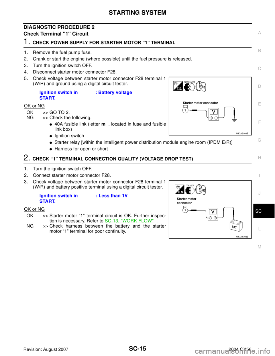
1. CHECK POWER SUPPLY FOR STARTER MOTOR “1” TERMINAL
1. Remove the fuel pump fuse.
2. Crank or start the engine (where possible) until the fuel pressure is released.
3. Turn the ignition switch OFF.
4. Disconnect starter motor connector F28.
5. Check voltage between starter motor connector F28 terminal 1
(W/R) and ground using a digital circuit tester.
OK or NG
OK >> GO TO 2.
NG >> Check the following.
�40A fusible link (letter m , located in fuse and fusible
link box)
�Ignition switch
�Starter relay [within the intelligent power distribution module engine room (IPDM E/R)]
�Harness for open or short
2. CHECK “1” TERMINAL CONNECTION QUALITY (VOLTAGE DROP TEST)
1. Turn the ignition switch OFF.
2. Connect starter motor connector F28.
3. Check voltage between starter motor connector F28 terminal 1
(W/R) and battery positive terminal using a digital circuit tester.
OK or NG
OK >> Starter motor “1” terminal circuit is OK. Further inspec-
tion is necessary. Refer to SC-13, "
WORK FLOW" .
NG >> Check harness between the battery and the starter
motor “1” terminal for poor continuity. Ignition switch in
START.: Battery voltage
WKIA2108E
Ignition switch in
START.: Less than 1V
WKIA1792E
Page 2937 of 3371
SC-16
STARTING SYSTEM
Revision: August 20072004 QX56
MINIMUM SPECIFICATION OF CRANKING VOLTAGE REFERENCING COOLANT TEMPERA-
TURE
Removal and InstallationEKS0079B
REMOVAL
1. Remove the intake manifold. Refer to EM-15, "Removal and Installation" .
2. Disconnect the starter harness connectors.
3. Remove the two starter bolts, using power tools.
4. Remove the starter.
INSTALLATION
Installation is in the reverse order of removal.
CAUTION:
Tighten terminal "2" nut carefully.
Engine coolant temperature Voltage V
−30°C to −20°C (−22°F to −4°F) 8.4
−19°C to −10°C (−2°F to 14°F) 8.9
−9°C to 0°C (16°F to 32°F) 9.3
More than 1°C (More than 34°F) 9.7
WKIA1388E
Terminal "2"nut : 10.8 N·m (1.1 kg-m, 8 ft-lb)
Page 2938 of 3371

CHARGING SYSTEM
SC-17
C
D
E
F
G
H
I
J
L
MA
B
SC
Revision: August 20072004 QX56
CHARGING SYSTEMPFP:23100
System DescriptionEKS0079E
The generator provides DC voltage to operate the vehicle's electrical system and to keep the battery charged.
The voltage output is controlled by the IC regulator.
Power is supplied at all times to generator terminal 4 through:
�10A fuse (No. 30, located in the fuse and fusible link box).
Terminal 1 supplies power to charge the battery and operate the vehicle's electrical system. Output voltage is
controlled by the IC regulator at terminal 4 detecting the input voltage. The charging circuit is protected by the
140A fusible link (letter a , located in the fusible link box).
Ground is supplied:
�to generator terminal 2
�through body ground E203.
With the ignition switch in the ON or START position, power is supplied:
�through 10A fuse [No. 14, located in the fuse block (J/B)]
�to combination meter terminal 24 for the charge warning lamp.
Ground is supplied to terminal 13 of the combination meter through terminal 3 of the generator. With power
and ground supplied, the charge warning lamp will illuminate. When the generator is providing sufficient volt-
age with the engine running, the ground is opened and the charge warning lamp will go off.
If the charge warning lamp illuminates with the engine running, a fault is indicated.