Page 2779 of 3371

PS-28
POWER STEERING OIL PUMP
Revision: August 20072004 QX56
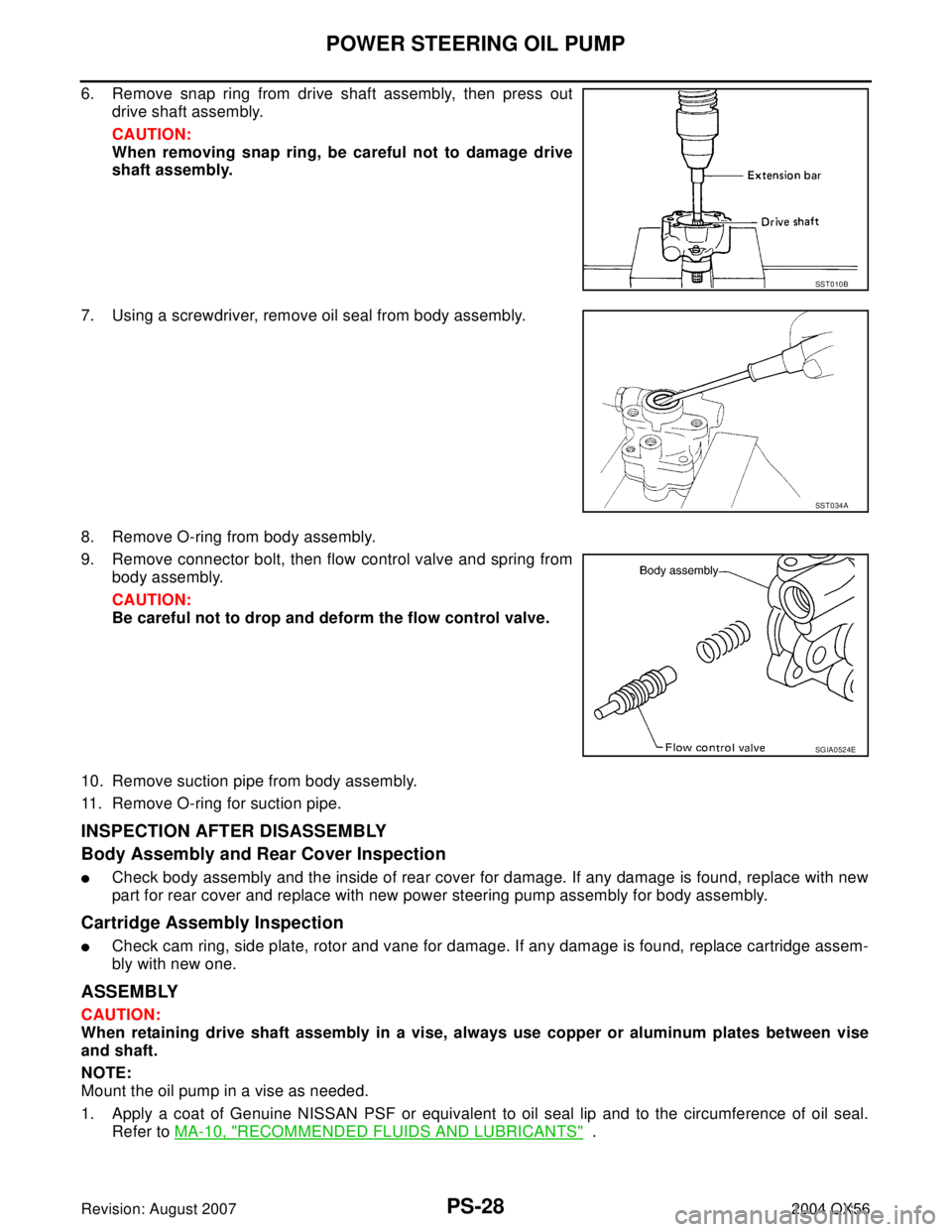
6. Remove snap ring from drive shaft assembly, then press out
drive shaft assembly.
CAUTION:
When removing snap ring, be careful not to damage drive
shaft assembly.
7. Using a screwdriver, remove oil seal from body assembly.
8. Remove O-ring from body assembly.
9. Remove connector bolt, then flow control valve and spring from
body assembly.
CAUTION:
Be careful not to drop and deform the flow control valve.
10. Remove suction pipe from body assembly.
11. Remove O-ring for suction pipe.
INSPECTION AFTER DISASSEMBLY
Body Assembly and Rear Cover Inspection
�Check body assembly and the inside of rear cover for damage. If any damage is found, replace with new
part for rear cover and replace with new power steering pump assembly for body assembly.
Cartridge Assembly Inspection
�Check cam ring, side plate, rotor and vane for damage. If any damage is found, replace cartridge assem-
bly with new one.
ASSEMBLY
CAUTION:
When retaining drive shaft assembly in a vise, always use copper or aluminum plates between vise
and shaft.
NOTE:
Mount the oil pump in a vise as needed.
1. Apply a coat of Genuine NISSAN PSF or equivalent to oil seal lip and to the circumference of oil seal.
Refer to MA-10, "
RECOMMENDED FLUIDS AND LUBRICANTS" .
SST 0 10 B
SST 0 34 A
SGIA0524E
Page 3270 of 3371

CENTER CASE
TF-145
C
E
F
G
H
I
J
K
L
MA
B
TF
Revision: August 20072004 QX56
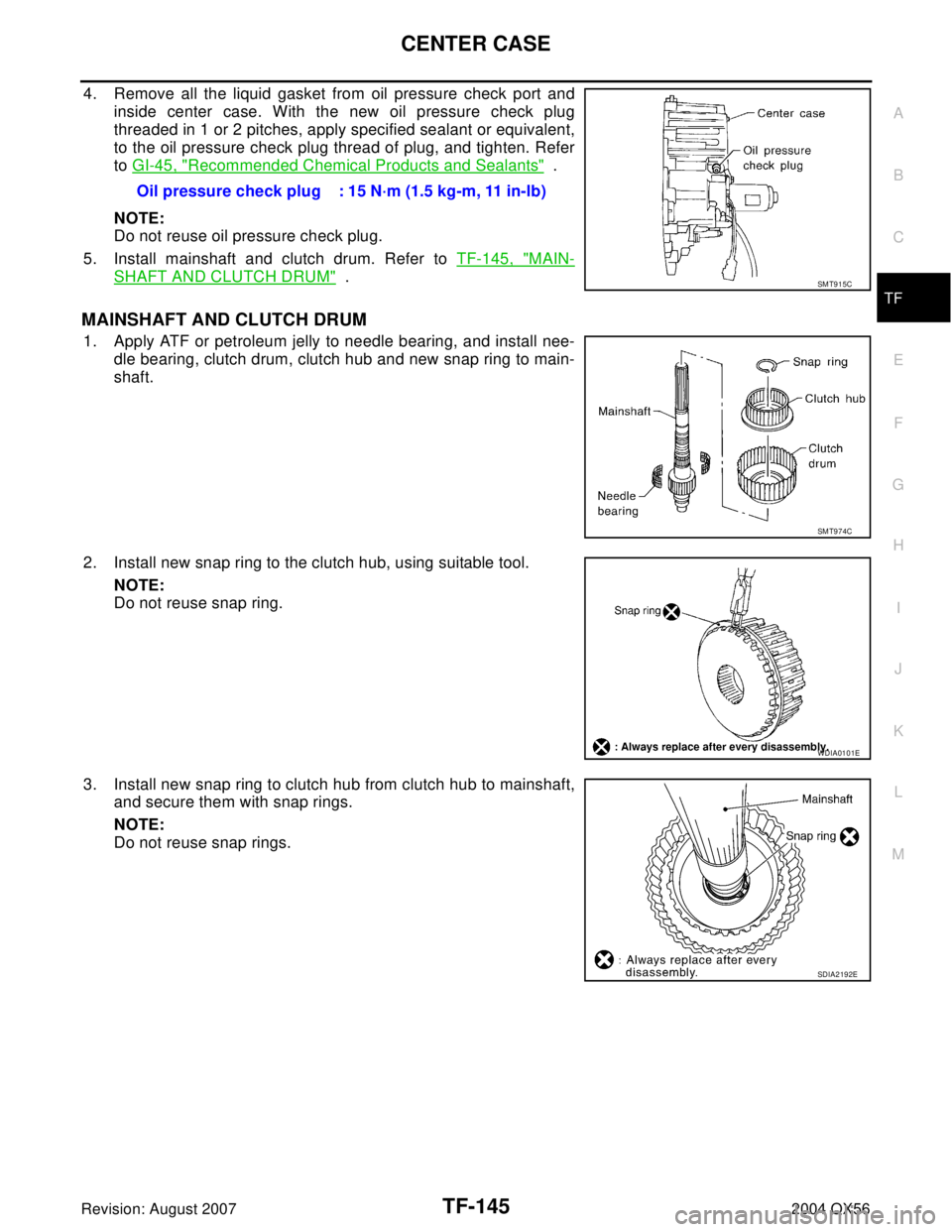
4. Remove all the liquid gasket from oil pressure check port and
inside center case. With the new oil pressure check plug
threaded in 1 or 2 pitches, apply specified sealant or equivalent,
to the oil pressure check plug thread of plug, and tighten. Refer
to GI-45, "
Recommended Chemical Products and Sealants" .
NOTE:
Do not reuse oil pressure check plug.
5. Install mainshaft and clutch drum. Refer to TF-145, "
MAIN-
SHAFT AND CLUTCH DRUM" .
MAINSHAFT AND CLUTCH DRUM
1. Apply ATF or petroleum jelly to needle bearing, and install nee-
dle bearing, clutch drum, clutch hub and new snap ring to main-
shaft.
2. Install new snap ring to the clutch hub, using suitable tool.
NOTE:
Do not reuse snap ring.
3. Install new snap ring to clutch hub from clutch hub to mainshaft,
and secure them with snap rings.
NOTE:
Do not reuse snap rings.Oil pressure check plug : 15 N·m (1.5 kg-m, 11 in-lb)
SMT915C
SMT974C
WDIA0101E
SDIA2192E
Page 3274 of 3371
ASSEMBLY
TF-149
C
E
F
G
H
I
J
K
L
MA
B
TF
Revision: August 20072004 QX56
ASSEMBLYPFP:00030
Final AssemblyEDS00195
1. Install C-rings to mainshaft.
2. Set washer holder on mainshaft, and secure it with new snap
ring.
NOTE:
Do not reuse snap ring.
3. Apply specified Anaerobic Liquid Gasket or equivalent to the
entire center case mounting surface of front case assembly as
shown. Refer to GI-45, "
Recommended Chemical Products and
Sealants" .
NOTE:
Remove all foreign materials such as water, oil and grease from
center case and front case mating surfaces.
SDIA2201E
SDIA2104E
SDIA2202E
Page 3275 of 3371

TF-150
ASSEMBLY
Revision: August 20072004 QX56
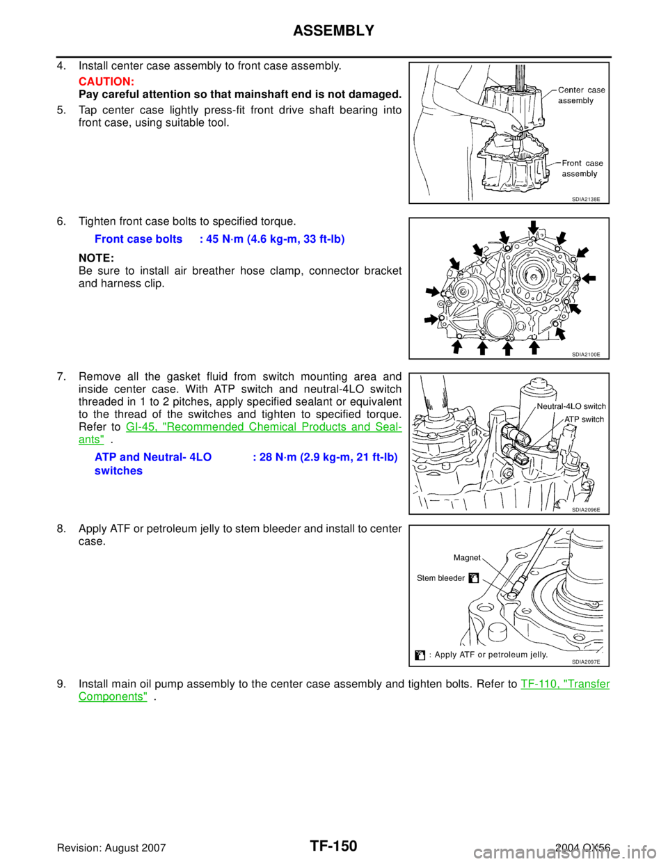
4. Install center case assembly to front case assembly.
CAUTION:
Pay careful attention so that mainshaft end is not damaged.
5. Tap center case lightly press-fit front drive shaft bearing into
front case, using suitable tool.
6. Tighten front case bolts to specified torque.
NOTE:
Be sure to install air breather hose clamp, connector bracket
and harness clip.
7. Remove all the gasket fluid from switch mounting area and
inside center case. With ATP switch and neutral-4LO switch
threaded in 1 to 2 pitches, apply specified sealant or equivalent
to the thread of the switches and tighten to specified torque.
Refer to GI-45, "
Recommended Chemical Products and Seal-
ants" .
8. Apply ATF or petroleum jelly to stem bleeder and install to center
case.
9. Install main oil pump assembly to the center case assembly and tighten bolts. Refer to TF-110, "
Transfer
Components" .
SDIA2138E
Front case bolts : 45 N·m (4.6 kg-m, 33 ft-lb)
SDIA2100E
ATP and Neutral- 4LO
switches: 28 N·m (2.9 kg-m, 21 ft-lb)
SDIA2096E
SDIA2097E
Page 3277 of 3371
TF-152
ASSEMBLY
Revision: August 20072004 QX56
15. Install air breather into rear case.
16. Apply specified Anaerobic Liquid Gasket or equivalent to entire
rear case mounting surface of center case as shown. Refer to
GI-45, "
Recommended Chemical Products and Sealants" .
CAUTION:
Be careful not to allow Liquid Gasket to the stem bleeder
hole.
NOTE:
Remove all foreign materials such as water, oil, and grease from
center case and rear case mating surfaces.
17. Install rear case to center case, and tighten bolts to specified
torque.
18. Installation of the remaining components is in the reverse order of removal.
SDIA2206E
Center case bolts : 45 N·m 4.6 kg-m, 33 ft-lb)
SDIA2100E