Page 1267 of 3371

EC-76Revision: August 2007
TROUBLE DIAGNOSIS
2004 QX56
DTC Inspection Priority ChartUBS00GZX
If some DTCs are displayed at the same time, perform inspections one by one based on the following priority
chart.
NOTE:
If DTC U1000 and/or U1001 is displayed with other DTC, first perform the trouble diagnosis for DTC
U1000, U1001. Refer to EC-135, "
DTC U1000, U1001 CAN COMMUNICATION LINE" .
Priority Detected items (DTC)
1
�U1000 U1001 CAN communication line
�P0101 P0102 P0103 Mass air flow sensor
�P0112 P0113 P0127 Intake air temperature sensor
�P0117 P0118 P0125 Engine coolant temperature sensor
�P0122 P0123 P0222 P0223 P1225 P1226 P2135 Throttle position sensor
�P0128 Thermostat function
�P0181 P0182 P0183 Fuel tank temperature sensor
�P0327 P0328 P0332 P0333 Knock sensor
�P0335 Crankshaft position sensor (POS)
�P0340 Camshaft position sensor (PHASE)
�P0460 P0461 P0462 P0463 Fuel level sensor
�P0500 Vehicle speed sensor
�P0605 ECM
�P0705 Park/Neutral position (PNP) switch
�P1229 Sensor power supply
�P1610 - P1615 NATS
�P1706 Park/Neutral position (PNP) switch
�P2122 P2123 P2127 P2128 P2138 Accelerator pedal position sensor
Page 1268 of 3371

TROUBLE DIAGNOSIS
EC-77
C
D
E
F
G
H
I
J
K
L
MA
EC
Revision: August 20072004 QX56
Fail-safe ChartUBS00GZY
When the DTC listed below is detected, the ECM enters fail-safe mode and the MIL lights up.
2�P0037 P0038 P0057 P0058 Heated oxygen sensor 2 heater
�P0138 P0139 P0158 P0159 P1146 P1147 P1166 P1167 Heated oxygen sensor 2
�P0441 EVAP control system purge flow monitoring
�P0444 P0445 P1444 EVAP canister purge volume control solenoid valve
�P0447 P1446 EVAP canister vent control valve
�P0451 P0452 P0453 EVAP control system pressure sensor
�P0550 Power steering pressure sensor
�P0700 P0710 P0720 P0740 P0744 P0745 P1706 P1716 P1730 P1752 P1754 P1757 P1759 P1762 P1764 P1767
P1769 P1772 P1774 A/T related sensors and solenoid valves
�P1031 P1032 P1051 P1052 A/F sensor 1 heater
�P1065 ECM power supply
�P1122 Electric throttle control function
�P1124 P1126 P1128 Electric throttle control actuator
�P1217 Engine over temperature (OVERHEAT)
�P1271 P1272 P1273 P1274 P1276 P1278 P1279 P1281 P1282 P1283 P1284 P1286 P1288 P1289 A/F sensor 1
�P1805 Brake switch
3
�P0171 P0172 P0174 P0175 Fuel injection system function
�P0300 - P0308 Misfire
�P0420 P0430 Three way catalyst function
�P0442 P0456 EVAP control system (SMALL LEAK, VERY SMALL LEAK)
�P0455 EVAP control system (GROSS LEAK)
�P0506 P0507 Idle speed control system
�P1121 Electric throttle control actuator
�P1148 P1168 Closed loop control
�P1211 TCS control unit
�P1212 TCS communication line
�P1564 ICC steering switch/ASCD steering switch
�P1568 ICC command value
�P1572 ICC brake switch/ASCD brake switch
�P1574 ICC vehicle speed sensor/ASCD vehicle speed sensor Priority Detected items (DTC)
DTC No. Detected items Engine operating condition in fail-safe mode
P0101
P0102
P0103Mass air flow sensor circuit Engine speed will not rise more than 2,400 rpm due to the fuel cut.
P0117
P0118Engine coolant tempera-
ture sensor circuitEngine coolant temperature will be determined by ECM based on the time after turning
ignition switch ON or START.
CONSULT-II displays the engine coolant temperature decided by ECM.
ConditionEngine coolant temperature decided
(CONSULT-II display)
Just as ignition switch is turned
ON or START40°C (104°F)
More than approx. 4 minutes after
ignition ON or START80°C (176°F)
Except as shown above40 - 80°C (104 - 176°F)
(Depends on the time)
When the fail-safe system for engine coolant temperature sensor is activated, the cooling
fan operates while engine is running.
Page 1292 of 3371
![INFINITI QX56 2004 Factory Service Manual TROUBLE DIAGNOSIS
EC-101
C
D
E
F
G
H
I
J
K
L
MA
EC
Revision: August 20072004 QX5670 B/W Refrigerant pressure sensor[Engine is running]�Warm-up condition
�Both A/C switch and blower switch are ON.
(Co INFINITI QX56 2004 Factory Service Manual TROUBLE DIAGNOSIS
EC-101
C
D
E
F
G
H
I
J
K
L
MA
EC
Revision: August 20072004 QX5670 B/W Refrigerant pressure sensor[Engine is running]�Warm-up condition
�Both A/C switch and blower switch are ON.
(Co](/manual-img/42/57034/w960_57034-1291.png)
TROUBLE DIAGNOSIS
EC-101
C
D
E
F
G
H
I
J
K
L
MA
EC
Revision: August 20072004 QX5670 B/W Refrigerant pressure sensor[Engine is running]�Warm-up condition
�Both A/C switch and blower switch are ON.
(Compressor operates.)1.0 - 4.0V
73 Y/BEngine coolant temperature
sensor[Engine is running]Approximately 0 - 4.8V
Output voltage varies with
engine coolant temperature.
74 LHeated oxygen sensor 2
(bank 2)[Engine is running]
�Warm-up condition
�Revving engine from idle to 3,000 rpm
quickly after the following conditions are
met.
–After keeping the engine speed between
3,500 and 4,000 rpm for 1 minute and at
idle for 1 minute under no load.0 - Approximately 1.0V
82 B/RSensor ground
(APP sensor 1)[Engine is running]
�Warm-up condition
�Idle speedApproximately 0V
83 G/WSensor ground
(APP sensor 2)[Engine is running]
�Warm-up condition
�Idle speedApproximately 0V
85 G/W Data link connector[Ignition switch: ON]
�CONSULT-II or GST is disconnected.Approximately 5V - Battery volt-
age (11 - 14V)
86 R CAN communication line[Ignition switch: ON]Approximately 1.1 - 2.3V
Output voltage varies with the
communication status.
90 LSensor power supply
(APP sensor 1)[Ignition switch: ON]Approximately 5V
91 W/RSensor power supply
(APP sensor 2)[Ignition switch: ON]Approximately 5V
94 W CAN communication line[Ignition switch: ON]Approximately 2.6 - 3.2V
Output voltage varies with the
communication status.
98 G/RAccelerator pedal position
sensor 2[Ignition switch: ON]
�Engine stopped
�Accelerator pedal: Fully released0.15 - 0.60V
[Ignition switch: ON]
�Engine stopped
�Accelerator pedal: Fully depressed1.95 - 2.40V TER-
MINAL
NO.WIRE
COLORITEM CONDITION DATA (DC Voltage)
Page 1294 of 3371

TROUBLE DIAGNOSIS
EC-103
C
D
E
F
G
H
I
J
K
L
MA
EC
Revision: August 20072004 QX56
: Average voltage for pulse signal (Actual pulse signal can be confirmed by oscilloscope.)
CONSULT-II FunctionUBS00H05
FUNCTION
*1: The following emission-related diagnostic information is cleared when the ECM memory is erased.
�Diagnostic trouble codes
�1st trip diagnostic trouble codes
�Freeze frame data
�1st trip freeze frame data 109 B/R Ignition switch[Ignition switch: OFF]0V
[Ignition switch: ON]BATTERY VOLTAGE
(11 - 14V)
111 W /BECM relay
(Self shut-off)[Engine is running]
[Ignition switch: OFF]
�For a few seconds after turning ignition
switch OFF0 - 1.5V
[Ignition switch: OFF]
�More than a few seconds after turning igni-
tion switch OFFBATTERY VOLTAGE
(11 - 14V)
113 GR Fuel pump relay[Ignition switch: ON]
�For 1 second after turning ignition switch
ON
[Engine is running]0 - 1.5V
[Ignition switch: ON]
�More than 1 second after turning ignition
switch ONBATTERY VOLTAGE
(11 - 14V)
11 5
11 6B
B/WECM ground[Engine is running]
�Idle speedBody ground
11 7 L / YEVAP canister vent control
valve[Ignition switch: ON]BATTERY VOLTAGE
(11 - 14V)
11 9
120BR
BRPower supply for ECM[Ignition switch: ON]BATTERY VOLTAGE
(11 - 14V)
121 WPower supply for ECM
(Back-up)[Ignition switch: OFF]BATTERY VOLTAGE
(11 - 14V) TER-
MINAL
NO.WIRE
COLORITEM CONDITION DATA (DC Voltage)
Diagnostic test mode Function
Work supportThis mode enables a technician to adjust some devices faster and more accurately by following the
indications on the CONSULT-II unit.
Self-diagnostic resultsSelf-diagnostic results such as 1st trip DTC, DTCs and 1st trip freeze frame data or freeze frame data
can be read and erased quickly.*
1
Data monitor Input/Output data in the ECM can be read.
Data monitor (SPEC)Input/Output of the specification for Basic fuel schedule, AFM, A/F feedback control value and the
other data monitor items can be read.
CAN diagnostic support
monotorThe results of transmit/receive diagnosis of CAN communication can be read.
Active testDiagnostic Test Mode in which CONSULT-II drives some actuators apart from the ECMs and also
shifts some parameters in a specified range.
DTC & SRT confirmation The status of system monitoring tests and the self-diagnosis status/result can be confirmed.
Function test This mode is used to inform customers when their vehicle condition requires periodic maintenance.
ECM part number ECM part number can be read.
Page 1296 of 3371

TROUBLE DIAGNOSIS
EC-105
C
D
E
F
G
H
I
J
K
L
MA
EC
Revision: August 20072004 QX56
X: Applicable
*1: This item includes 1st trip DTCs.
*2: This mode includes 1st trip freeze frame data or freeze frame data. The items appear on CONSULT-II screen in freeze frame data
mode only if a 1st trip DTC or DTC is detected. For details, refer to EC-54, "
FREEZE FRAME DATA AND 1ST TRIP FREEZE FRAME
DATA" .
INSPECTION PROCEDURE
CAUTION:
If CONSULT-II is used with no connection of CONSULT-II CONVERTER, malfunctions might be
detected in self-diagnosis depending on control unit which carry out CAN communication.
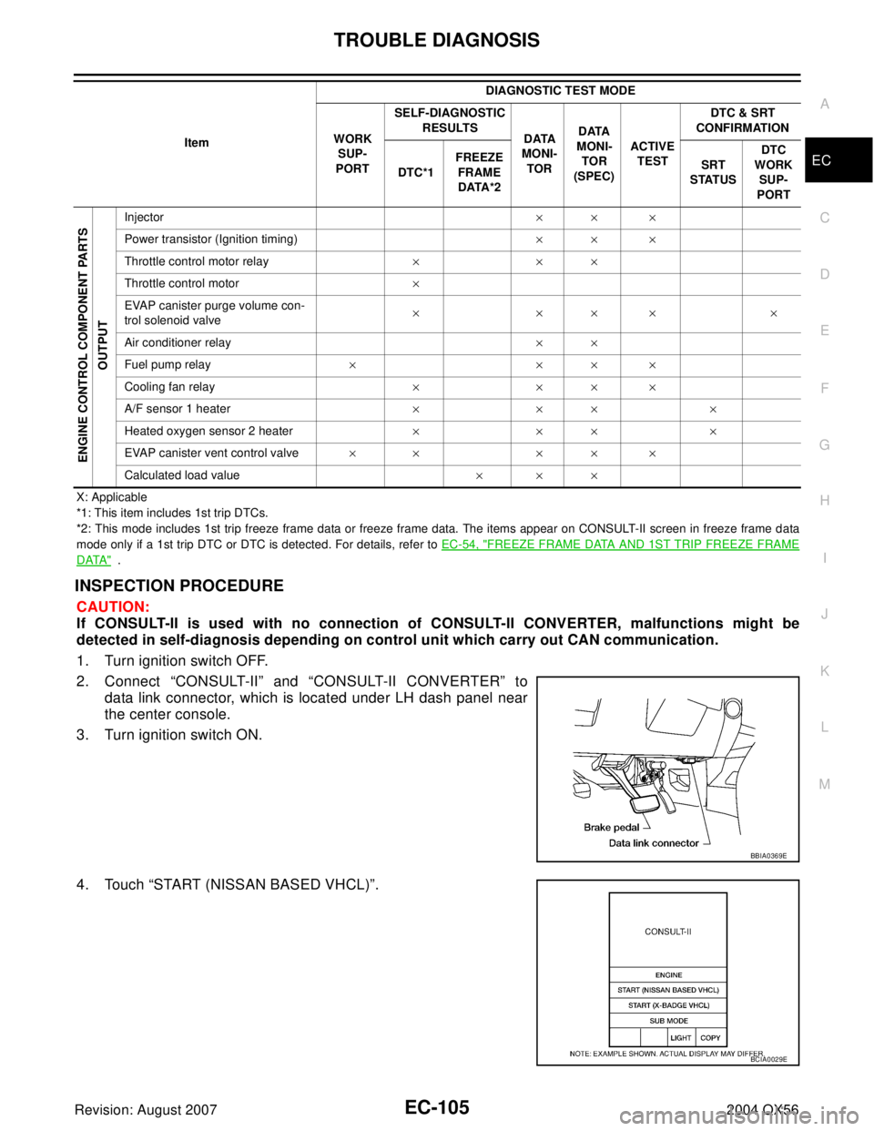
1. Turn ignition switch OFF.
2. Connect “CONSULT-II” and “CONSULT-II CONVERTER” to
data link connector, which is located under LH dash panel near
the center console.
3. Turn ignition switch ON.
4. Touch “START (NISSAN BASED VHCL)”.
ENGINE CONTROL COMPONENT PARTS
OUTPUT
Injector×× ×
Power transistor (Ignition timing)×× ×
Throttle control motor relay×××
Throttle control motor×
EVAP canister purge volume con-
trol solenoid valve×××××
Air conditioner relay××
Fuel pump relay××××
Cooling fan relay××××
A/F sensor 1 heater××××
Heated oxygen sensor 2 heater××××
EVAP canister vent control valve×× ×××
Calculated load value××× ItemDIAGNOSTIC TEST MODE
WORK
SUP-
PORTSELF-DIAGNOSTIC
RESULTS
DATA
MONI-
TORDATA
MONI-
TOR
(SPEC)ACTIVE
TESTDTC & SRT
CONFIRMATION
DTC*1FREEZE
FRAME
DATA*2SRT
STATUSDTC
WORK
SUP-
PORT
BBIA0369E
BCIA0029E
Page 1326 of 3371

DTC U1000, U1001 CAN COMMUNICATION LINE
EC-135
C
D
E
F
G
H
I
J
K
L
MA
EC
Revision: August 20072004 QX56
DTC U1000, U1001 CAN COMMUNICATION LINEPFP:23710
DescriptionUBS00H0I
CAN (Controller Area Network) is a serial communication line for real time application. It is an on-vehicle mul-
tiplex communication line with high data communication speed and excellent error detection ability. Many elec-
tronic control units are equipped onto a vehicle, and each control unit shares information and links with other
control units during operation (not independent). In CAN communication, control units are connected with 2
communication lines (CAN H line, CAN L line) allowing a high rate of information transmission with less wiring.
Each control unit transmits/receives data but selectively reads required data only.
On Board Diagnosis LogicUBS00H0J
*1: This self-diagnosis has the one trip detection logic.
*2: The MIL will not light up for this diagnosis.
DTC Confirmation ProcedureUBS00H0K
1. Turn ignition switch ON and wait at least 3 seconds.
2. Select “DATA MONITOR” mode with CONSULT-II.
3. If 1st trip DTC is detected, go to EC-137, "
Diagnostic Procedure" .
DTC No. Trouble diagnosis name DTC detecting condition Possible cause
U1000*
1
1000*1
CAN communication line
�ECM cannot communicate to other control
units.
�ECM cannot communicate for more than the
specified time.
�Harness or connectors
(CAN communication line is open or
shorted) U1001*
2
1001*2
Page 1327 of 3371
EC-136Revision: August 2007
DTC U1000, U1001 CAN COMMUNICATION LINE
2004 QX56
Wiring DiagramUBS00H0L
BBWA0873E
Page 1328 of 3371
DTC U1000, U1001 CAN COMMUNICATION LINE
EC-137
C
D
E
F
G
H
I
J
K
L
MA
EC
Revision: August 20072004 QX56
Diagnostic ProcedureUBS00H0M
Go to LAN-3, "Precautions When Using CONSULT-II" .