Page 3216 of 3371

TROUBLE DIAGNOSES FOR SYMPTOMS
TF-91
C
E
F
G
H
I
J
K
L
MA
B
TF
Revision: August 20072004 QX56
3. CHECK 4LO INDICATOR LAMP CIRCUIT AND COMBINATION METER
Check the following.
�Combination meter. Refer to DI-17, "How to Proceed With Trouble Diagnosis" .
�Continuity between ignition switch and combination meter
�Continuity between combination meter and transfer control unit
�Condition of ATP and neutral-4LO switch circuit. Refer to TF-69, "ATP SWITCH, WAIT DETECTION
SWITCH AND NEUTRAL-4LO SWITCH" .
OK or NG
OK >> Replace transfer control unit. Refer to TF-98, "Removal and Installation" .
NG >>
�Repair or replace harness or connector.
�Replace combination meter. Refer to DI-25, "Removal and Installation of Combination Meter" .
�Replace ATP or neutral-4LO switch.
Symptom 6. 4WD Shift Indicator Lamp Does Not Indicate “LOCK” (When 4WD
shift switch is set to “4H”, 4WD shift indicator lamp does not indicate “LOCK”)
EDS0018J
1. CHECK 4WD WARNING LAMP
Is 4WD warning lamp turned ON?
Ye s o r N o
Yes >> Refer to TF-27, "Trouble Diagnosis without CONSULT-
II" .
No >> GO TO 2.
2. CHECK NEUTRAL-4LO, WAIT DETECTION AND ATP SWITCH CIRCUITS
Check neutral-4LO, wait detection and ATP switch circuits. Refer to TF-69, "
ATP SWITCH, WAIT DETECTION
SWITCH AND NEUTRAL-4LO SWITCH" .
OK or NG
OK >> GO TO 3.
NG >> Check, repair or replace faulty parts.
3. CHECK PROCEDURES FROM THE BEGINNING AGAIN
Check again.
OK or NG
OK >> Inspection End.
NG >> Recheck each connector pin terminals for damage or loose connection.
WDIA0071E
Page 3218 of 3371

TROUBLE DIAGNOSES FOR SYMPTOMS
TF-93
C
E
F
G
H
I
J
K
L
MA
B
TF
Revision: August 20072004 QX56
Symptom 8. Tight Corner Braking Symptom (Tight Corner Braking Symptom
Occurs-Hydraulic System Failure)
EDS0018L
1. CHECK INPUT SIGNAL
With CONSULT-II
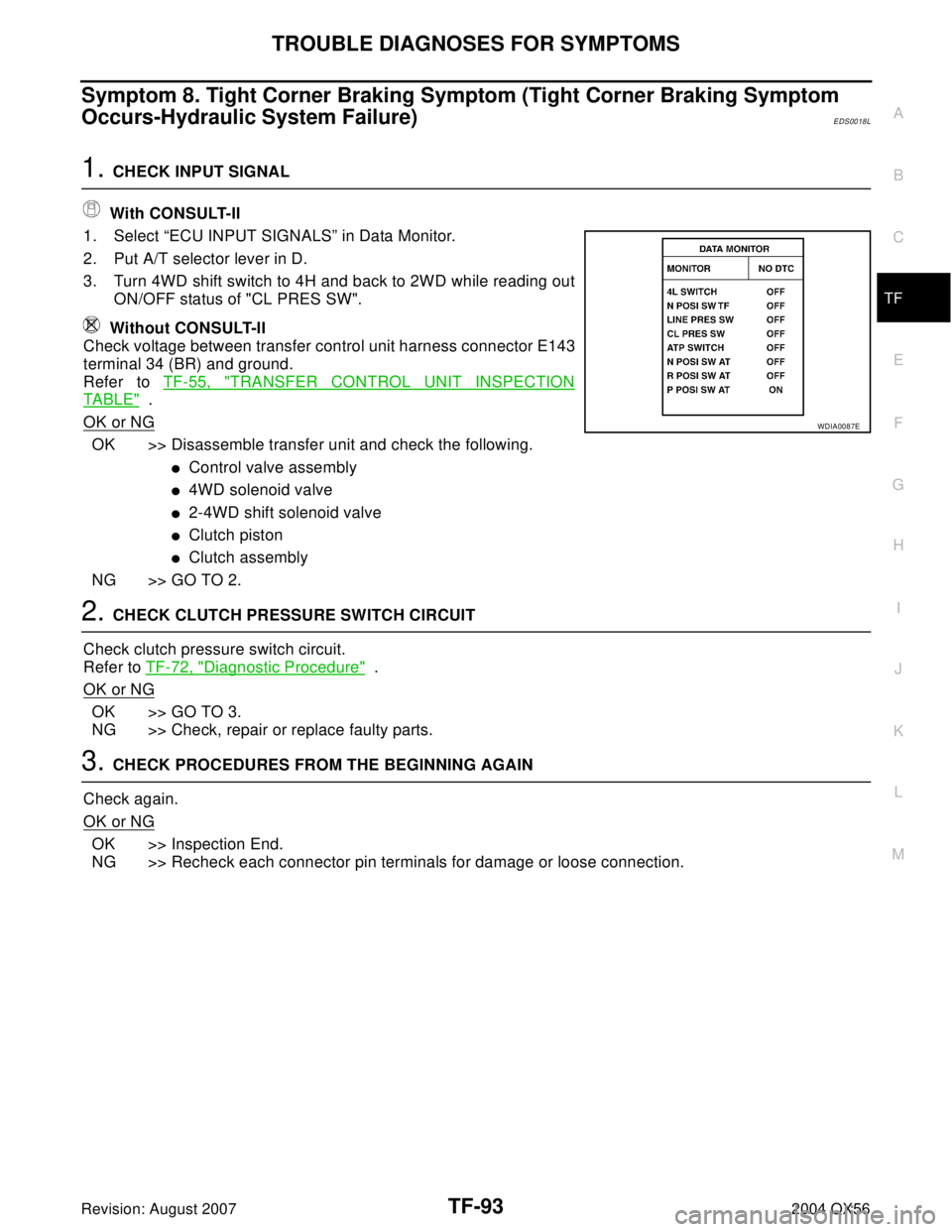
1. Select “ECU INPUT SIGNALS” in Data Monitor.
2. Put A/T selector lever in D.
3. Turn 4WD shift switch to 4H and back to 2WD while reading out
ON/OFF status of "CL PRES SW".
Without CONSULT-II
Check voltage between transfer control unit harness connector E143
terminal 34 (BR) and ground.
Refer to TF-55, "
TRANSFER CONTROL UNIT INSPECTION
TABLE" .
OK or NG
OK >> Disassemble transfer unit and check the following.
�Control valve assembly
�4WD solenoid valve
�2-4WD shift solenoid valve
�Clutch piston
�Clutch assembly
NG >> GO TO 2.
2. CHECK CLUTCH PRESSURE SWITCH CIRCUIT
Check clutch pressure switch circuit.
Refer to TF-72, "
Diagnostic Procedure" .
OK or NG
OK >> GO TO 3.
NG >> Check, repair or replace faulty parts.
3. CHECK PROCEDURES FROM THE BEGINNING AGAIN
Check again.
OK or NG
OK >> Inspection End.
NG >> Recheck each connector pin terminals for damage or loose connection.
WDIA0087E
Page 3219 of 3371

TF-94
TROUBLE DIAGNOSES FOR SYMPTOMS
Revision: August 20072004 QX56
Symptom 9. 4WD System Does Not Operate (The Vehicle Cannot Be Put Into
4WD Mode-Hydraulic System Failure)
EDS0018M
1. CHECK INPUT SIGNAL
With CONSULT-II
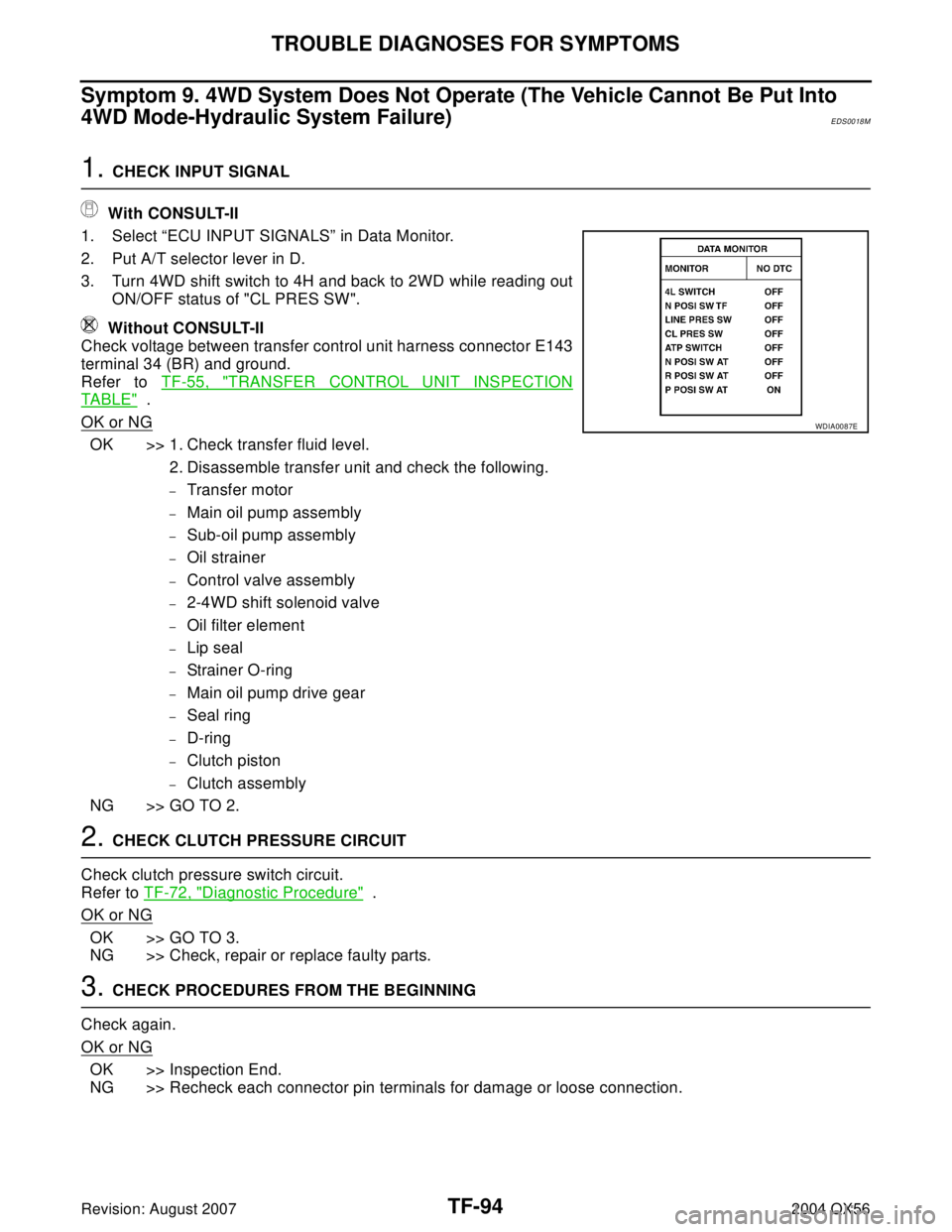
1. Select “ECU INPUT SIGNALS” in Data Monitor.
2. Put A/T selector lever in D.
3. Turn 4WD shift switch to 4H and back to 2WD while reading out
ON/OFF status of "CL PRES SW".
Without CONSULT-II
Check voltage between transfer control unit harness connector E143
terminal 34 (BR) and ground.
Refer to TF-55, "
TRANSFER CONTROL UNIT INSPECTION
TABLE" .
OK or NG
OK >> 1. Check transfer fluid level.
2. Disassemble transfer unit and check the following.
–Transfer motor
–Main oil pump assembly
–Sub-oil pump assembly
–Oil strainer
–Control valve assembly
–2-4WD shift solenoid valve
–Oil filter element
–Lip seal
–Strainer O-ring
–Main oil pump drive gear
–Seal ring
–D-ring
–Clutch piston
–Clutch assembly
NG >> GO TO 2.
2. CHECK CLUTCH PRESSURE CIRCUIT
Check clutch pressure switch circuit.
Refer to TF-72, "
Diagnostic Procedure" .
OK or NG
OK >> GO TO 3.
NG >> Check, repair or replace faulty parts.
3. CHECK PROCEDURES FROM THE BEGINNING
Check again.
OK or NG
OK >> Inspection End.
NG >> Recheck each connector pin terminals for damage or loose connection.
WDIA0087E
Page 3230 of 3371
AIR BREATHER HOSE
TF-105
C
E
F
G
H
I
J
K
L
MA
B
TF
Revision: August 20072004 QX56
AIR BREATHER HOSEPFP:31098
Removal and InstallationEDS00319
Refer to the figure for air breather hose removal and installation information.
CAUTION:
�Make sure there are no pinched or restricted areas on the air breather hose caused by bending or
winding when installing it.
�Install the air breather hose into the air breather (metal connector) and actuator (case connector)
until the hose end reaches the base of the tube.
�Install the air breather hose into the breather tube (metal connector) and transfer motor (case con-
nector) until the hose end reaches the end of the curved section.
SDIA2656E
Page 3236 of 3371
OVERHAUL
TF-111
C
E
F
G
H
I
J
K
L
MA
B
TF
Revision: August 20072004 QX56
46. Snap ring 47. Retaining pin 48. L-H fork
49. 2-4 fork 50. Shift fork spring 51. Fork guide
52. Retainer pin 53. Shift rod
1. Dust cover 2. Oil seal 3. Rear case
4. Air breather 5. Seal ring 6. Main oil pump cover
7. Inner gear 8. Outer gear 9. Main oil pump housing
10. D-ring 11. D-ring 12. Clutch piston
13. Thrust needle bearing race 14. Oil strainer 15. O-ring
16. Snap ring 17. Control valve assembly 18. Lip seal (7 pieces)
19. Washer 20. Filler plug 21. Filler stud
22. O-ring 23. Oil filter 24. ATP switch
25 Neutral-4LO switch 26. Oil pressure check plug 27. Harness bracket
28. Stem bleeder 29. Harness bracket 30. Center case
31. Mainshaft rear bearing 32. C-ring 33. Washer holder
34. Snap ring 35. Sub oil pump housing 36. Outer gear
37. Inner gear 38. Sub oil pump cover 39. O-ring
40. Transfer motor 41. Connector bracket
SDIA2091E
Page 3237 of 3371
TF-112
REAR CASE
Revision: August 20072004 QX56
REAR CASEPFP:33102
DisassemblyEDS0018Y
1. Remove rear case bolts.
2. Remove rear case from center case, using suitable tool.
3. Remove the dust cover, using suitable tool.
4. Remove the oil seal, using suitable tool.
CAUTION:
Be careful not to damage the rear case.
5. Remove the air breather.
SDIA2092E
SDIA2093E
SDIA2094E
SDIA2095E
Page 3243 of 3371
TF-118
CENTER CASE
Revision: August 20072004 QX56
10. Tap mainshaft, using suitable tool to remove it from clutch drum
and clutch hub.
11. Remove needle bearing and spacer from the mainshaft.
12. Remove the snap ring from the clutch hub.
CLUTCH PISTON
1. Remove oil pressure check plug from oil pressure check port.
2. Apply air gradually from oil pressure check port, and remove
clutch piston from center case.
SMT914C
WDIA0101E
SDIA2 115 E
SDIA2 116 E
Page 3267 of 3371
TF-142
CENTER CASE
Revision: August 20072004 QX56
CONTROL VALVE
1. Clean upper body, control valves and springs with cleaning agent, and dry with compressed air.
2. Dip control valves in ATF, and apply ATF to the valve-mounting area of upper body.
3. Install each control valve (3), spring (4) and plug (2) to upper
body (5), and install retainer plates (1) to hold them in place.
CAUTION:
�To insert control valves into upper body, place upper
body on a level surface in order to prevent flaw or dam-
age.
�Make sure each control valve is smoothly inserted.
4. Install reverse balls, relief balls and relief springs, accumulator
pistons and valve springs to upper body.
5. Install lower body and separator plate to upper body.
NOTE:
Do not reuse separator plates.
WDIA0284E
SDIA2127E
SDIA2126E
SDIA2125E