Page 1276 of 3371
TROUBLE DIAGNOSIS
EC-85
C
D
E
F
G
H
I
J
K
L
MA
EC
Revision: August 20072004 QX56
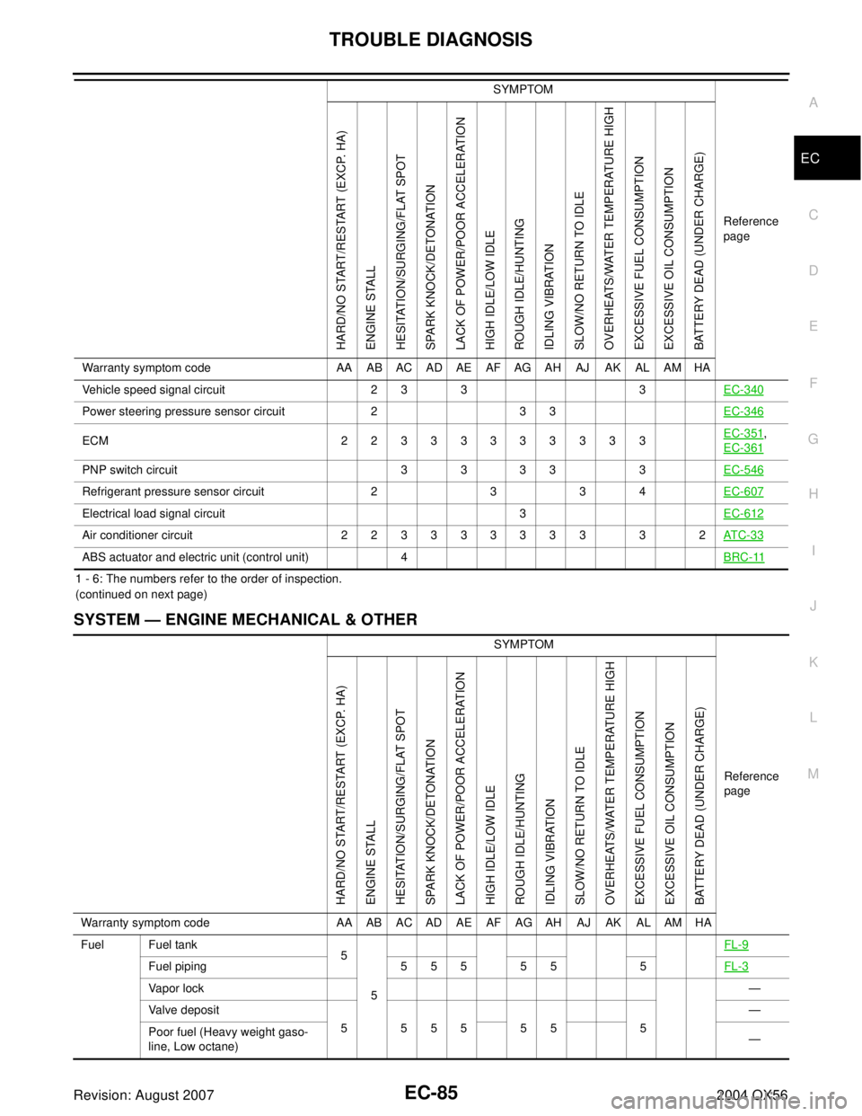
1 - 6: The numbers refer to the order of inspection.
(continued on next page)
SYSTEM — ENGINE MECHANICAL & OTHER
Vehicle speed signal circuit 2 3 3 3EC-340
Power steering pressure sensor circuit 2 3 3EC-346
ECM 22333333333EC-351,
EC-361
PNP switch circuit 3 3 3 3 3EC-546
Refrigerant pressure sensor circuit 2 3 3 4EC-607
Electrical load signal circuit 3EC-612
Air conditioner circuit 2 2 3 3 3 3 3 3 3 3 2AT C - 3 3
ABS actuator and electric unit (control unit) 4BRC-11
SYMPTOM
Reference
page
HARD/NO START/RESTART (EXCP. HA)
ENGINE STALL
HESITATION/SURGING/FLAT SPOT
SPARK KNOCK/DETONATION
LACK OF POWER/POOR ACCELERATION
HIGH IDLE/LOW IDLE
ROUGH IDLE/HUNTING
IDLING VIBRATION
SLOW/NO RETURN TO IDLE
OVERHEATS/WATER TEMPERATURE HIGH
EXCESSIVE FUEL CONSUMPTION
EXCESSIVE OIL CONSUMPTION
BATTERY DEAD (UNDER CHARGE)
Warranty symptom code AA AB AC AD AE AF AG AH AJ AK AL AM HA
Fuel Fuel tank
5
5FL-9
Fuel piping 5 5 5 5 5 5FL-3
Vapor lock—
Valve deposit
555555 5—
Poor fuel (Heavy weight gaso-
line, Low octane)—
Page 1532 of 3371
DTC P0500 VSS
EC-341
C
D
E
F
G
H
I
J
K
L
MA
EC
Revision: August 20072004 QX56
2. Start engine.
3. Read vehicle speed sensor signal in MODE 1 with GST.
The vehicle speed sensor on GST should be able to exceed 10 km/h (6 MPH) when rotating wheels with
suitable gear position.
4. If NG, go to EC-341, "
Diagnostic Procedure" .
Diagnostic ProcedureUBS00H6G
1. CHECK DTC WITH ABS ACTUATOR AND ELECTRIC UNIT (CONTROL UNIT)
Refer to BRC-11, "
TROUBLE DIAGNOSIS" .
OK or NG
OK >> GO TO 2.
NG >> Repair or replace.
2. CHECK DTC WITH COMBINATION METER
Refer to DI-5, "
COMBINATION METERS" .
>>INSPECTION END
Page 1599 of 3371
EC-408Revision: August 2007
DTC P1211 TCS CONTROL UNIT
2004 QX56
DTC P1211 TCS CONTROL UNITPFP:47850
DescriptionUBS00H8L
The malfunction information related to TCS is transferred through the CAN communication line from “ABS
actuator and electric unit (control unit)” to ECM.
Be sure to erase the malfunction information such as DTC not only for “ABS actuator and electric unit
(control unit)” but also for ECM after TCS related repair.
On Board Diagnosis LogicUBS00H8M
Freeze frame data is not stored in the ECM for this self-diagnosis.
The MIL will not light up for this self-diagnosis.
DTC Confirmation ProcedureUBS00H8N
TESTING CONDITION:
Before performing the following procedure, confirm that battery voltage is more than 10.5V at idle.
WITH CONSULT-II
1. Turn ignition switch ON.
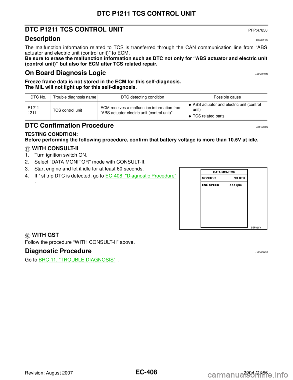
2. Select “DATA MONITOR” mode with CONSULT-II.
3. Start engine and let it idle for at least 60 seconds.
4. If 1st trip DTC is detected, go to EC-408, "
Diagnostic Procedure"
.
WITH GST
Follow the procedure “WITH CONSULT-II” above.
Diagnostic ProcedureUBS00H8O
Go to BRC-11, "TROUBLE DIAGNOSIS" .
DTC No. Trouble diagnosis name DTC detecting condition Possible cause
P1211
1211TCS control unitECM receives a malfunction information from
“ABS actuator electric unit (control unit)”
�ABS actuator and electric unit (control
unit)
�TCS related parts
SEF 0 58 Y
Page 1600 of 3371
DTC P1212 TCS COMMUNICATION LINE
EC-409
C
D
E
F
G
H
I
J
K
L
MA
EC
Revision: August 20072004 QX56
DTC P1212 TCS COMMUNICATION LINEPFP:47850
DescriptionUBS00H8P
NOTE:
If DTC P1212 is displayed with DTC U1000 or U1001, first perform the trouble diagnosis for DTC U1000,
U1001. Refer to EC-135, "
DTC U1000, U1001 CAN COMMUNICATION LINE" .
This CAN communication line is used to control the smooth engine operation during the TCS operation. Pulse
signals are exchanged between ECM and “ABS actuator and electric unit (control unit)”.
Be sure to erase the malfunction information such as DTC not only for “ABS actuator and electric unit
(control unit)” but also for ECM after TCS related repair.
On Board Diagnosis LogicUBS00H8Q
Freeze frame data is not stored in the ECM for this self-diagnosis.
The MIL will not light up for this self-diagnosis.
DTC Confirmation ProcedureUBS00H8R
TESTING CONDITION:
Before performing the following procedure, confirm that battery voltage is more than 10.5V at idle.
WITH CONSULT-II
1. Turn ignition switch ON.
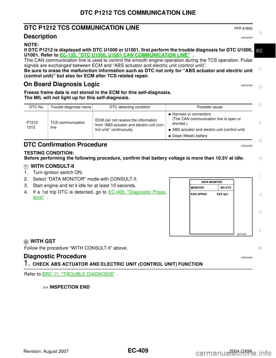
2. Select “DATA MONITOR” mode with CONSULT-II.
3. Start engine and let it idle for at least 10 seconds.
4. If a 1st trip DTC is detected, go to EC-409, "
Diagnostic Proce-
dure" .
WITH GST
Follow the procedure “WITH CONSULT-II” above.
Diagnostic ProcedureUBS00H8S
1. CHECK ABS ACTUATOR AND ELECTRIC UNIT (CONTROL UNIT) FUNCTION
Refer to BRC-11, "
TROUBLE DIAGNOSIS" .
>>INSPECTION END
DTC No. Trouble diagnosis name DTC detecting condition Possible cause
P1212
1212TCS communication
lineECM can not receive the information
from “ABS actuator and electric unit (con-
trol unit)” continuously.
�Harness or connectors
(The CAN communication line is open or
shorted.)
�ABS actuator and electric unit (control unit)
�Dead (Weak) battery
SEF 0 58 Y
Page 1734 of 3371
DTC P1574 ICC VEHICLE SPEED SENSOR
EC-543
C
D
E
F
G
H
I
J
K
L
MA
EC
Revision: August 20072004 QX56
Diagnostic ProcedureUBS00HZ9
1. CHECK DTC WITH TCM
Check DTC with TCM. Refer to AT - 3 9 , "
OBD-II Diagnostic Trouble Code (DTC)" .
OK or NG
OK >> GO TO 2.
NG >> Perform trouble shooting relevant to DTC indicated.
2. CHECK DTC WITH “ABS ACTUATOR AND ELECTRIC UNIT (CONTROL UNIT)”
Refer to BRC-11, "
TROUBLE DIAGNOSIS" .
OK or NG
OK >> GO TO 3.
NG >> Repair or replace.
3. CHECK DTC WITH “UNIFIED METER AND A/C AMP”
Refer to DI-5, "
COMBINATION METERS" .
>>INSPECTION END
Page 1736 of 3371
DTC P1574 ASCD VEHICLE SPEED SENSOR
EC-545
C
D
E
F
G
H
I
J
K
L
MA
EC
Revision: August 20072004 QX56
Diagnostic ProcedureUBS00HBP
1. CHECK DTC WITH TCM
Check DTC with TCM. Refer to AT - 3 9 , "
OBD-II Diagnostic Trouble Code (DTC)" .
OK or NG
OK >> GO TO 2.
NG >> Perform trouble shooting relevant to DTC indicated.
2. CHECK DTC WITH ABS ACTUATOR AND ELECTRIC UNIT (CONTROL UNIT)
Refer to BRC-11, "
TROUBLE DIAGNOSIS" .
OK or NG
OK >> GO TO 3.
NG >> Repair or replace.
3. CHECK COMBINATION METER
Check combination meter function.
Refer to DI-5, "
COMBINATION METERS" .
>>INSPECTION END
Page 2003 of 3371
FAX-6
WHEEL HUB
Revision: August 20072004 QX56
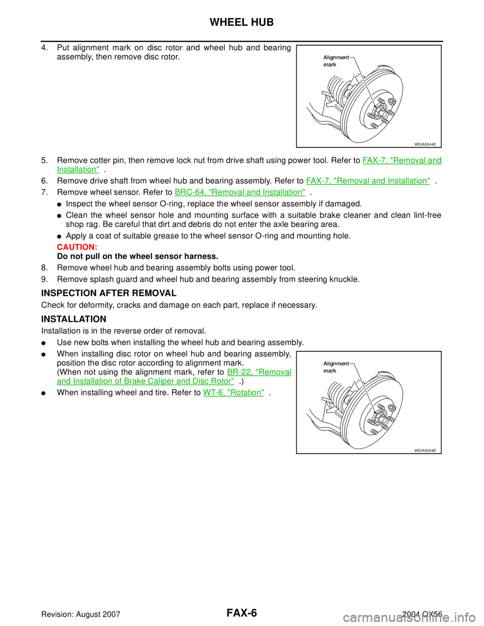
4. Put alignment mark on disc rotor and wheel hub and bearing
assembly, then remove disc rotor.
5. Remove cotter pin, then remove lock nut from drive shaft using power tool. Refer to FA X -7 , "
Removal and
Installation" .
6. Remove drive shaft from wheel hub and bearing assembly. Refer to FAX-7, "
Removal and Installation" .
7. Remove wheel sensor. Refer to BRC-64, "
Removal and Installation" .
�Inspect the wheel sensor O-ring, replace the wheel sensor assembly if damaged.
�Clean the wheel sensor hole and mounting surface with a suitable brake cleaner and clean lint-free
shop rag. Be careful that dirt and debris do not enter the axle bearing area.
�Apply a coat of suitable grease to the wheel sensor O-ring and mounting hole.
CAUTION:
Do not pull on the wheel sensor harness.
8. Remove wheel hub and bearing assembly bolts using power tool.
9. Remove splash guard and wheel hub and bearing assembly from steering knuckle.
INSPECTION AFTER REMOVAL
Check for deformity, cracks and damage on each part, replace if necessary.
INSTALLATION
Installation is in the reverse order of removal.
�Use new bolts when installing the wheel hub and bearing assembly.
�When installing disc rotor on wheel hub and bearing assembly,
position the disc rotor according to alignment mark.
(When not using the alignment mark, refer to BR-22, "
Removal
and Installation of Brake Caliper and Disc Rotor" .)
�When installing wheel and tire. Refer to WT-6, "Rotation" .
WDIA0044E
WDIA0044E
Page 2076 of 3371
KNUCKLE
FSU-17
C
D
F
G
H
I
J
K
L
MA
B
FSU
Revision: August 20072004 QX56
KNUCKLEPFP:40014
On-Vehicle Inspection and ServiceEES0010R
Make sure the mounting conditions (looseness, backlash) of each component and component status (wear,
damage) are within specifications. Refer to FSU-21, "
Ball Joint" .
Removal and InstallationEES0010S
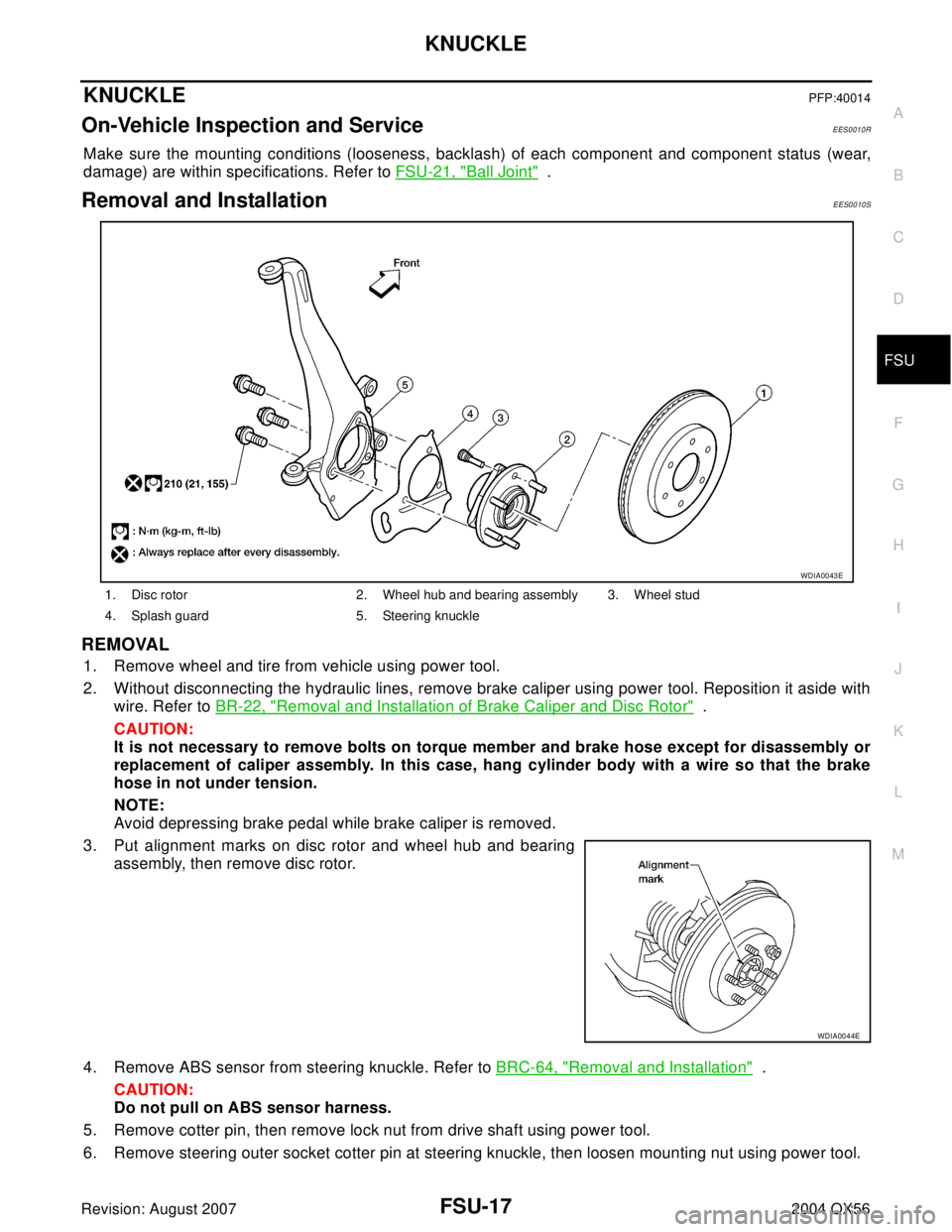
REMOVAL
1. Remove wheel and tire from vehicle using power tool.
2. Without disconnecting the hydraulic lines, remove brake caliper using power tool. Reposition it aside with
wire. Refer to BR-22, "
Removal and Installation of Brake Caliper and Disc Rotor" .
CAUTION:
It is not necessary to remove bolts on torque member and brake hose except for disassembly or
replacement of caliper assembly. In this case, hang cylinder body with a wire so that the brake
hose in not under tension.
NOTE:
Avoid depressing brake pedal while brake caliper is removed.
3. Put alignment marks on disc rotor and wheel hub and bearing
assembly, then remove disc rotor.
4. Remove ABS sensor from steering knuckle. Refer to BRC-64, "
Removal and Installation" .
CAUTION:
Do not pull on ABS sensor harness.
5. Remove cotter pin, then remove lock nut from drive shaft using power tool.
6. Remove steering outer socket cotter pin at steering knuckle, then loosen mounting nut using power tool.
1. Disc rotor 2. Wheel hub and bearing assembly 3. Wheel stud
4. Splash guard 5. Steering knuckle
WDIA0043E
WDIA0044E