Page 1610 of 4449
DTC P0172, P0175 FUEL INJECTION SYSTEM FUNCTION
EC-269
[VQ35DE]
C
D
E
F
G
H
I
J
K
L
MA
EC
Revision: 2004 November 2004 FX35/FX45
Diagnostic ProcedureABS006P5
1. CHECK EXHAUST GAS LEAK
1. Start engine and run it at idle.
2. Listen for an exhaust gas leak before three way catalyst 1.
OK or NG
OK >> GO TO 2.
NG >> Repair or replace.
2. CHECK FOR INTAKE AIR LEAK
Listen for an intake air leak after the mass air flow sensor.
OK or NG
OK >> GO TO 3.
NG >> Repair or replace.
PBIB1165E
Page 1612 of 4449
DTC P0172, P0175 FUEL INJECTION SYSTEM FUNCTION
EC-271
[VQ35DE]
C
D
E
F
G
H
I
J
K
L
MA
EC
Revision: 2004 November 2004 FX35/FX45
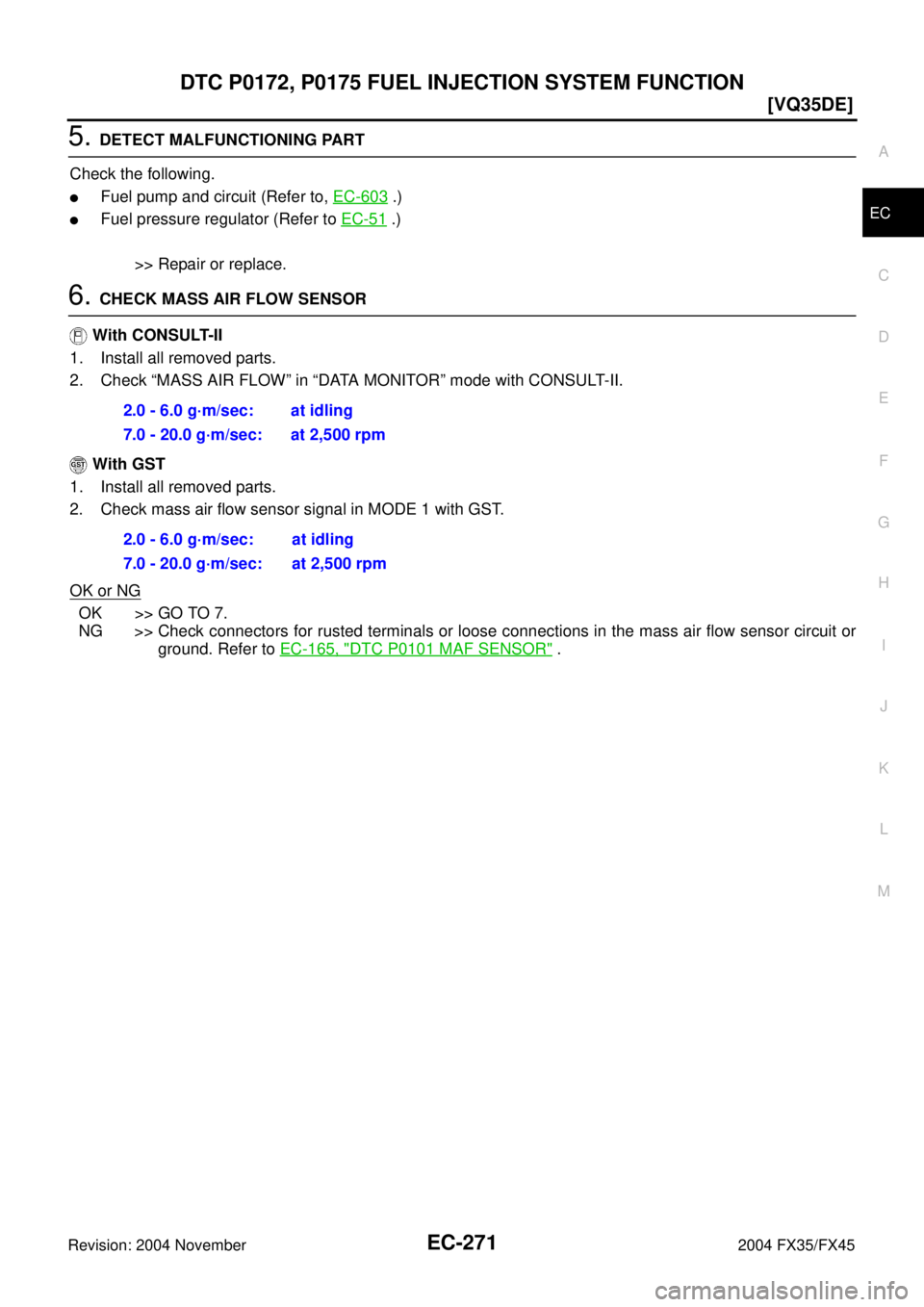
5. DETECT MALFUNCTIONING PART
Check the following.
�Fuel pump and circuit (Refer to, EC-603 .)
�Fuel pressure regulator (Refer to EC-51 .)
>> Repair or replace.
6. CHECK MASS AIR FLOW SENSOR
With CONSULT-II
1. Install all removed parts.
2. Check “MASS AIR FLOW” in “DATA MONITOR” mode with CONSULT-II.
With GST
1. Install all removed parts.
2. Check mass air flow sensor signal in MODE 1 with GST.
OK or NG
OK >> GO TO 7.
NG >> Check connectors for rusted terminals or loose connections in the mass air flow sensor circuit or
ground. Refer to EC-165, "
DTC P0101 MAF SENSOR" . 2.0 - 6.0 g·m/sec: at idling
7.0 - 20.0 g·m/sec: at 2,500 rpm
2.0 - 6.0 g·m/sec: at idling
7.0 - 20.0 g·m/sec: at 2,500 rpm
Page 1636 of 4449
![INFINITI FX35 2004 Service Manual DTC P0300 - P0306 MULTIPLE CYLINDER MISFIRE, NO. 1 - 6 CYLINDER MIS-
FIRE
EC-295
[VQ35DE]
C
D
E
F
G
H
I
J
K
L
MA
EC
Revision: 2004 November 2004 FX35/FX45
9. DETECT MALFUNCTIONING PART
Check the follo](/manual-img/42/57021/w960_57021-1635.png "INFINITI FX35 2004 Service Manual DTC P0300 - P0306 MULTIPLE CYLINDER MISFIRE, NO. 1 - 6 CYLINDER MIS-
FIRE
EC-295
[VQ35DE]
C
D
E
F
G
H
I
J
K
L
MA
EC
Revision: 2004 November 2004 FX35/FX45
9. DETECT MALFUNCTIONING PART
Check the follo")
DTC P0300 - P0306 MULTIPLE CYLINDER MISFIRE, NO. 1 - 6 CYLINDER MIS-
FIRE
EC-295
[VQ35DE]
C
D
E
F
G
H
I
J
K
L
MA
EC
Revision: 2004 November 2004 FX35/FX45
9. DETECT MALFUNCTIONING PART
Check the following.
�Fuel pump and circuit (Refer to EC-603 .)
�Fuel pressure regulator (Refer to EC-51 .)
�Fuel lines
�Fuel filter for clogging
>> Repair or replace.
10. CHECK IGNITION TIMING
Check the following items. Refer to EC-83, "
Basic Inspection" .
OK or NG
OK >> GO TO 11.
NG >> Follow the EC-83, "
Basic Inspection" .
11 . CHECK HEATED OXYGEN SENSOR 1 (BANK 1)/(BANK 2)
Refer to EC-212, "
Component Inspection" .
OK or NG
OK >> GO TO 12.
NG >> Replace (malfunctioning) heated oxygen sensor 1.
12. CHECK MASS AIR FLOW SENSOR
With CONSULT-II
Check mass air flow sensor signal in “DATA MONITOR” mode with CONSULT-II.
With GST
Check mass air flow sensor signal in MODE 1 with GST.
OK or NG
OK >> GO TO 13.
NG >> Check connectors for rusted terminals or loose connections in the mass air flow sensor circuit or
ground. Refer to EC-165, "
DTC P0101 MAF SENSOR" .
13. CHECK SYMPTOM MATRIX CHART
Check items on the rough idle symptom in EC-88, "
Symptom Matrix Chart" .
OK or NG
OK >> GO TO 14.
NG >> Repair or replace.
Items Specifications
Target idle speed 650 ± 50 rpm (in P or N position)
Ignition timing 15 ± 5° BTDC (in P or N position)
2.0 - 6.0 g·m/sec: at idling
7.0 - 20.0 g·m/sec: at 2,500 rpm
2.0 - 6.0 g·m/sec: at idling
7.0 - 20.0 g·m/sec: at 2,500 rpm
Page 1659 of 4449
![INFINITI FX35 2004 Service Manual EC-318
[VQ35DE]
DTC P0420, P0430 THREE WAY CATALYST FUNCTION
Revision: 2004 November 2004 FX35/FX45
7. Make sure that the voltage switching frequency (high & low)
between ECM terminals 74 and ground,](/manual-img/42/57021/w960_57021-1658.png "INFINITI FX35 2004 Service Manual EC-318
[VQ35DE]
DTC P0420, P0430 THREE WAY CATALYST FUNCTION
Revision: 2004 November 2004 FX35/FX45
7. Make sure that the voltage switching frequency (high & low)
between ECM terminals 74 and ground,")
EC-318
[VQ35DE]
DTC P0420, P0430 THREE WAY CATALYST FUNCTION
Revision: 2004 November 2004 FX35/FX45
7. Make sure that the voltage switching frequency (high & low)
between ECM terminals 74 and ground, or 55 and ground is
very less than that of ECM terminals 35 and ground, or 16 and
ground.
Switching frequency ratio = A/B
A: Heated oxygen sensor 2 voltage switching frequency
B: Heated oxygen sensor 1 voltage switching frequency
This ratio should be less than 0.75.
If the ratio is greater than above, it means three way catalyst 1
does not operate properly. Go to EC-318, "
Diagnostic Proce-
dure" .
NOTE:
If the voltage at terminal 35 or 16 does not switch periodically more than 5 times within 10 seconds at step 7,
perform trouble diagnosis for DTC P0133, P0153 first. (See EC-214
.)
Diagnostic ProcedureABS006QK
1. CHECK EXHAUST SYSTEM
Visually check exhaust tubes and muffler for dent.
OK or NG
OK >> GO TO 2.
NG >> Repair or replace.
2. CHECK EXHAUST GAS LEAK
1. Start engine and run it at idle.
2. Listen for an exhaust gas leak before the three way catalyst 1.
OK or NG
OK >> GO TO 3.
NG >> Repair or replace.
3. CHECK INTAKE AIR LEAK
Listen for an intake air leak after the mass air flow sensor.
OK or NG
OK >> GO TO 4.
NG >> Repair or replace.
PBIB1108E
PBIB1165E
Page 1676 of 4449
![INFINITI FX35 2004 Service Manual DTC P0444, P0445 EVAP CANISTER PURGE VOLUME CONTROL SOLENOID
VALVE
EC-335
[VQ35DE]
C
D
E
F
G
H
I
J
K
L
MA
EC
Revision: 2004 November 2004 FX35/FX45
DTC P0444, P0445 EVAP CANISTER PURGE VOLUME CONTROL](/manual-img/42/57021/w960_57021-1675.png "INFINITI FX35 2004 Service Manual DTC P0444, P0445 EVAP CANISTER PURGE VOLUME CONTROL SOLENOID
VALVE
EC-335
[VQ35DE]
C
D
E
F
G
H
I
J
K
L
MA
EC
Revision: 2004 November 2004 FX35/FX45
DTC P0444, P0445 EVAP CANISTER PURGE VOLUME CONTROL")
DTC P0444, P0445 EVAP CANISTER PURGE VOLUME CONTROL SOLENOID
VALVE
EC-335
[VQ35DE]
C
D
E
F
G
H
I
J
K
L
MA
EC
Revision: 2004 November 2004 FX35/FX45
DTC P0444, P0445 EVAP CANISTER PURGE VOLUME CONTROL SOLENOID
VA LV E
PFP:14920
DescriptionABS006QT
SYSTEM DESCRIPTION
*1:ECM determines the start signal status by the signals of engine speed and battery voltage.
*2: This signal is sent to the ECM through CAN communication line.
This system controls flow rate of fuel vapor from the EVAP canister. The opening of the vapor by-pass pas-
sage in the EVAP canister purge volume control solenoid valve changes to control the flow rate. The EVAP
canister purge volume control solenoid valve repeats ON/OFF operation according to the signal sent from the
ECM. The opening of the valve varies for optimum engine control. The optimum value stored in the ECM is
determined by considering various engine conditions. When the engine is operating, the flow rate of fuel vapor
from the EVAP canister is regulated as the air flow changes.
COMPONENT DESCRIPTION
The EVAP canister purge volume control solenoid valve uses a ON/
OFF duty to control the flow rate of fuel vapor from the EVAP canis-
ter. The EVAP canister purge volume control solenoid valve is
moved by ON/OFF pulses from the ECM. The longer the ON pulse,
the greater the amount of fuel vapor that will flow through the valve.
CONSULT-II Reference Value in Data Monitor ModeABS006QU
Specification data are reference values.
Sensor Input signal to ECM ECM function Actuator
Crankshaft position sensor (POS)
Camshaft position sensor (PHASE)Engine speed*
1
EVAP canister
purge flow controlEVAP canister purge vol-
ume control solenoid valve Mass air flow sensor Amount of intake air
Engine coolant temperature sensor Engine coolant temperature
Battery
Battery voltage*
1
Throttle position sensor Throttle position
Accelerator pedal position sensor Accelerator pedal position
Heated oxygen sensors 1Density of oxygen in exhaust gas
(Mixture ratio feedback signal)
Fuel tank temperature sensor Fuel temperature in fuel tank
Wheel sensor*
2Vehicle speed
SEF337U
MONITOR ITEM CONDITION SPECIFICATION
PURG VOL C/V
�Engine: After warming up
�Shift lever: P or N
�Air conditioner switch: OFF
�No-loadIdle 0%
2,000 rpm —
Page 1734 of 4449
DTC P0506 ISC SYSTEM
EC-393
[VQ35DE]
C
D
E
F
G
H
I
J
K
L
MA
EC
Revision: 2004 November 2004 FX35/FX45
Diagnostic ProcedureABS006SH
1. CHECK INTAKE AIR LEAK
1. Start engine and let it idle.
2. Listen for an intake air leak after the mass air flow sensor.
OK or NG
OK >> GO TO 2.
NG >> Discover air leak location and repair.
2. REPLACE ECM
1. Stop engine.
2. Replace ECM.
3. Perform initialization of IVIS(NATS) system and registration of all IVIS(NATS) ignition key IDs. Refer to
BL-208, "
ECM Re-communicating Function" .
4. Perform EC-49, "
Accelerator Pedal Released Position Learning" .
5. Perform EC-49, "
Throttle Valve Closed Position Learning" .
6. Perform EC-49, "
Idle Air Volume Learning" .
>>INSPECTION END
Page 1736 of 4449
DTC P0507 ISC SYSTEM
EC-395
[VQ35DE]
C
D
E
F
G
H
I
J
K
L
MA
EC
Revision: 2004 November 2004 FX35/FX45
Diagnostic ProcedureABS006SL
1. CHECK PCV HOSE CONNECTION
Confirm that PCV hose is connected correctly.
OK or NG
OK >> GO TO 2.
NG >> Repair or replace.
2. CHECK INTAKE AIR LEAK
1. Start engine and let it idle.
2. Listen for an intake air leak after the mass air flow sensor.
OK or NG
OK >> GO TO 3.
NG >> Discover air leak location and repair.
3. REPLACE ECM
1. Stop engine.
2. Replace ECM.
3. Perform initialization of IVIS(NATS) system and registration of all IVIS(NATS) ignition key IDs. Refer to
BL-208, "
ECM Re-communicating Function" .
4. Perform EC-49, "
Accelerator Pedal Released Position Learning" .
5. Perform EC-49, "
Throttle Valve Closed Position Learning" .
6. Perform EC-49, "
Idle Air Volume Learning" .
>>INSPECTION END
Page 1777 of 4449
![INFINITI FX35 2004 Service Manual EC-436
[VQ35DE]
DTC P1143, P1163 HO2S1
Revision: 2004 November 2004 FX35/FX45
3. CLEAR THE SELF-LEARNING DATA
With CONSULT-II
1. Start engine and warm it up to normal operating temperature.
2. Select](/manual-img/42/57021/w960_57021-1776.png "INFINITI FX35 2004 Service Manual EC-436
[VQ35DE]
DTC P1143, P1163 HO2S1
Revision: 2004 November 2004 FX35/FX45
3. CLEAR THE SELF-LEARNING DATA
With CONSULT-II
1. Start engine and warm it up to normal operating temperature.
2. Select")
EC-436
[VQ35DE]
DTC P1143, P1163 HO2S1
Revision: 2004 November 2004 FX35/FX45
3. CLEAR THE SELF-LEARNING DATA
With CONSULT-II
1. Start engine and warm it up to normal operating temperature.
2. Select “SELF-LEARNING CONT” in “WORK SUPPORT” mode with CONSULT-II.
3. Clear the self-learning control coefficient by touching “CLEAR”.
4. Run engine for at least 10 minutes at idle speed.
Is the 1st trip DTC P0171 or P0174 detected?
Is it difficult to start engine?
Without CONSULT-II
1. Start engine and warm it up to normal operating temperature.
2. Turn ignition switch OFF.
3. Disconnect mass air flow sensor harness connector, and restart
and run engine for at least 5 seconds at idle speed.
4. Stop engine and reconnect mass air flow sensor harness con-
nector.
5. Make sure DTC P0102 is displayed.
6. Erase the DTC memory. Refer to EC-67, "
HOW TO ERASE
EMISSION-RELATED DIAGNOSTIC INFORMATION" .
7. Make sure DTC P0000 is displayed.
8. Run engine for at least 10 minutes at idle speed.
Is the 1st trip DTC P0171 or P0174 detected?
Is it difficult to start engine?
Ye s o r N o
Yes >> Perform trouble diagnosis for DTC P0171 or P0174. Refer to EC-256 .
No >> GO TO 4.
4. CHECK HEATED OXYGEN SENSOR 1 HEATER
Refer to EC-156, "
Component Inspection" .
OK or NG
OK >> GO TO 5.
NG >> Replace malfunctioning heated oxygen sensor 1.
5. CHECK HEATED OXYGEN SENSOR 1
Refer to EC-437, "
Component Inspection" .
OK or NG
OK >> GO TO 6.
NG >> Replace malfunctioning heated oxygen sensor 1.
6. CHECK INTERMITTENT INCIDENT
Refer to EC-135, "
TROUBLE DIAGNOSIS FOR INTERMITTENT INCIDENT" .
For circuit, refer to EC-207, "
Wiring Diagram" .
>>INSPECTION END
SEF968Y
PBIB1565E
![INFINITI FX35 2004 Service Manual DTC P0172, P0175 FUEL INJECTION SYSTEM FUNCTION
EC-269
[VQ35DE]
C
D
E
F
G
H
I
J
K
L
MA
EC
Revision: 2004 November 2004 FX35/FX45
Diagnostic ProcedureABS006P5
1. CHECK EXHAUST GAS LEAK
1. Start engine](/manual-img/42/57021/w960_57021-1609.png "INFINITI FX35 2004 Service Manual DTC P0172, P0175 FUEL INJECTION SYSTEM FUNCTION
EC-269
[VQ35DE]
C
D
E
F
G
H
I
J
K
L
MA
EC
Revision: 2004 November 2004 FX35/FX45
Diagnostic ProcedureABS006P5
1. CHECK EXHAUST GAS LEAK
1. Start engine")
![INFINITI FX35 2004 Service Manual DTC P0506 ISC SYSTEM
EC-393
[VQ35DE]
C
D
E
F
G
H
I
J
K
L
MA
EC
Revision: 2004 November 2004 FX35/FX45
Diagnostic ProcedureABS006SH
1. CHECK INTAKE AIR LEAK
1. Start engine and let it idle.
2. Listen f](/manual-img/42/57021/w960_57021-1733.png "INFINITI FX35 2004 Service Manual DTC P0506 ISC SYSTEM
EC-393
[VQ35DE]
C
D
E
F
G
H
I
J
K
L
MA
EC
Revision: 2004 November 2004 FX35/FX45
Diagnostic ProcedureABS006SH
1. CHECK INTAKE AIR LEAK
1. Start engine and let it idle.
2. Listen f")
![INFINITI FX35 2004 Service Manual DTC P0507 ISC SYSTEM
EC-395
[VQ35DE]
C
D
E
F
G
H
I
J
K
L
MA
EC
Revision: 2004 November 2004 FX35/FX45
Diagnostic ProcedureABS006SL
1. CHECK PCV HOSE CONNECTION
Confirm that PCV hose is connected corre](/manual-img/42/57021/w960_57021-1735.png "INFINITI FX35 2004 Service Manual DTC P0507 ISC SYSTEM
EC-395
[VQ35DE]
C
D
E
F
G
H
I
J
K
L
MA
EC
Revision: 2004 November 2004 FX35/FX45
Diagnostic ProcedureABS006SL
1. CHECK PCV HOSE CONNECTION
Confirm that PCV hose is connected corre")