2004 INFINITI FX35 window control
[x] Cancel search: window controlPage 3247 of 4449
GW-88
REAR WINDOW DEFOGGER
Revision: 2004 November 2004 FX35/FX45
CAN Communication System DescriptionAIS004R0
CAN (Controller Area Network) is a serial communication line for real time application. It is an on-vehicle mul-
tiplex communication line with high data communication speed and excellent error detection ability. Many elec-
tronic control units are equipped onto a vehicle, and each control unit shares information and links with other
control units during operation (not independent). In CAN communication, control units are connected with 2
communication lines (CAN H line, CAN L line) allowing a high rate of information transmission with less wiring.
Each control unit transmits/receives data but selectively reads required data only.
CAN Communication UnitAIS004RR
Refer to LAN-6, "CAN Communication Unit" .
Page 3253 of 4449
GW-94
REAR WINDOW DEFOGGER
Revision: 2004 November 2004 FX35/FX45
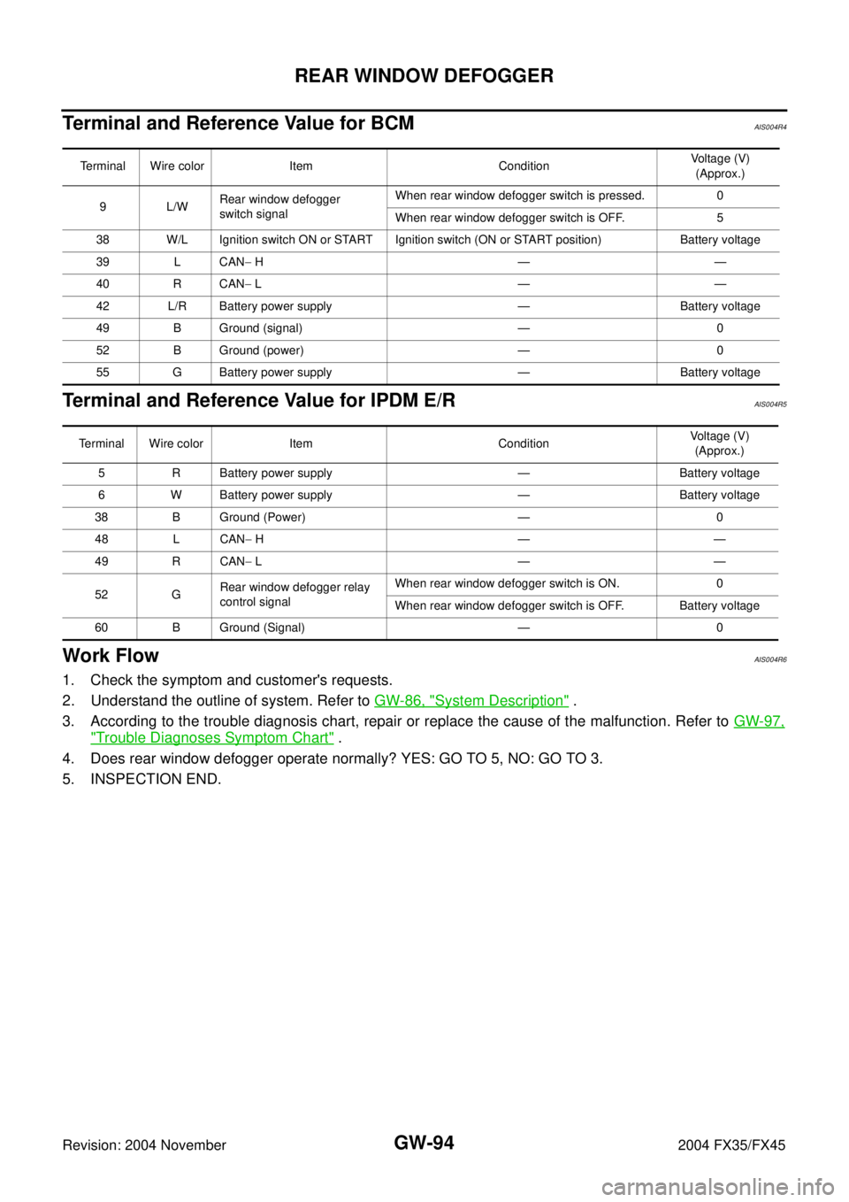
Terminal and Reference Value for BCMAIS004R4
Terminal and Reference Value for IPDM E/RAIS004R5
Work FlowAIS004R6
1. Check the symptom and customer's requests.
2. Understand the outline of system. Refer to GW-86, "
System Description" .
3. According to the trouble diagnosis chart, repair or replace the cause of the malfunction. Refer to GW-97,
"Trouble Diagnoses Symptom Chart" .
4. Does rear window defogger operate normally? YES: GO TO 5, NO: GO TO 3.
5. INSPECTION END.
Terminal Wire color Item ConditionVoltage (V)
(Approx.)
9L/WRear window defogger
switch signalWhen rear window defogger switch is pressed. 0
When rear window defogger switch is OFF. 5
38 W/L Ignition switch ON or START Ignition switch (ON or START position) Battery voltage
39 L CAN− H——
40 R CAN− L——
42 L/R Battery power supply — Battery voltage
49 B Ground (signal) — 0
52 B Ground (power) — 0
55 G Battery power supply — Battery voltage
Terminal Wire color Item ConditionVoltage (V)
(Approx.)
5 R Battery power supply — Battery voltage
6 W Battery power supply — Battery voltage
38 B Ground (Power) — 0
48 L CAN− H——
49 R CAN− L——
52 GRear window defogger relay
control signalWhen rear window defogger switch is ON. 0
When rear window defogger switch is OFF. Battery voltage
60 B Ground (Signal) — 0
Page 3254 of 4449
REAR WINDOW DEFOGGER
GW-95
C
D
E
F
G
H
J
K
L
MA
B
GW
Revision: 2004 November 2004 FX35/FX45
CONSULT-II Inspection ProcedureAIS004R7
CAUTION:
If CONSULT-II is used with no connection of CONSULT-II CONVERTER, malfunctions might be
detected in self-diagnosis depending on control unit which carry out CAN communication.
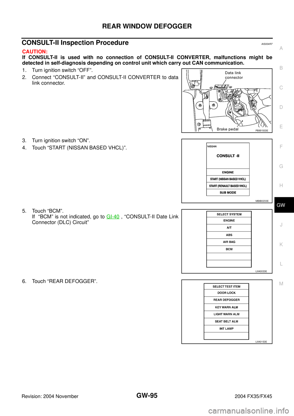
1. Turn ignition switch “OFF”.
2. Connect “CONSULT-II” and CONSULT-II CONVERTER to data
link connector.
3. Turn ignition switch “ON”.
4. Touch “START (NISSAN BASED VHCL)”.
5. Touch “BCM”.
If “BCM” is not indicated, go to GI-40
, “CONSULT-II Date Link
Connector (DLC) Circuit”
6. Touch “REAR DEFOGGER”.
PBIB1503E
MBIB0233E
LIIA0033E
LIIA0153E
Page 3265 of 4449
GW-106
REAR WINDOW DEFOGGER
Revision: 2004 November 2004 FX35/FX45
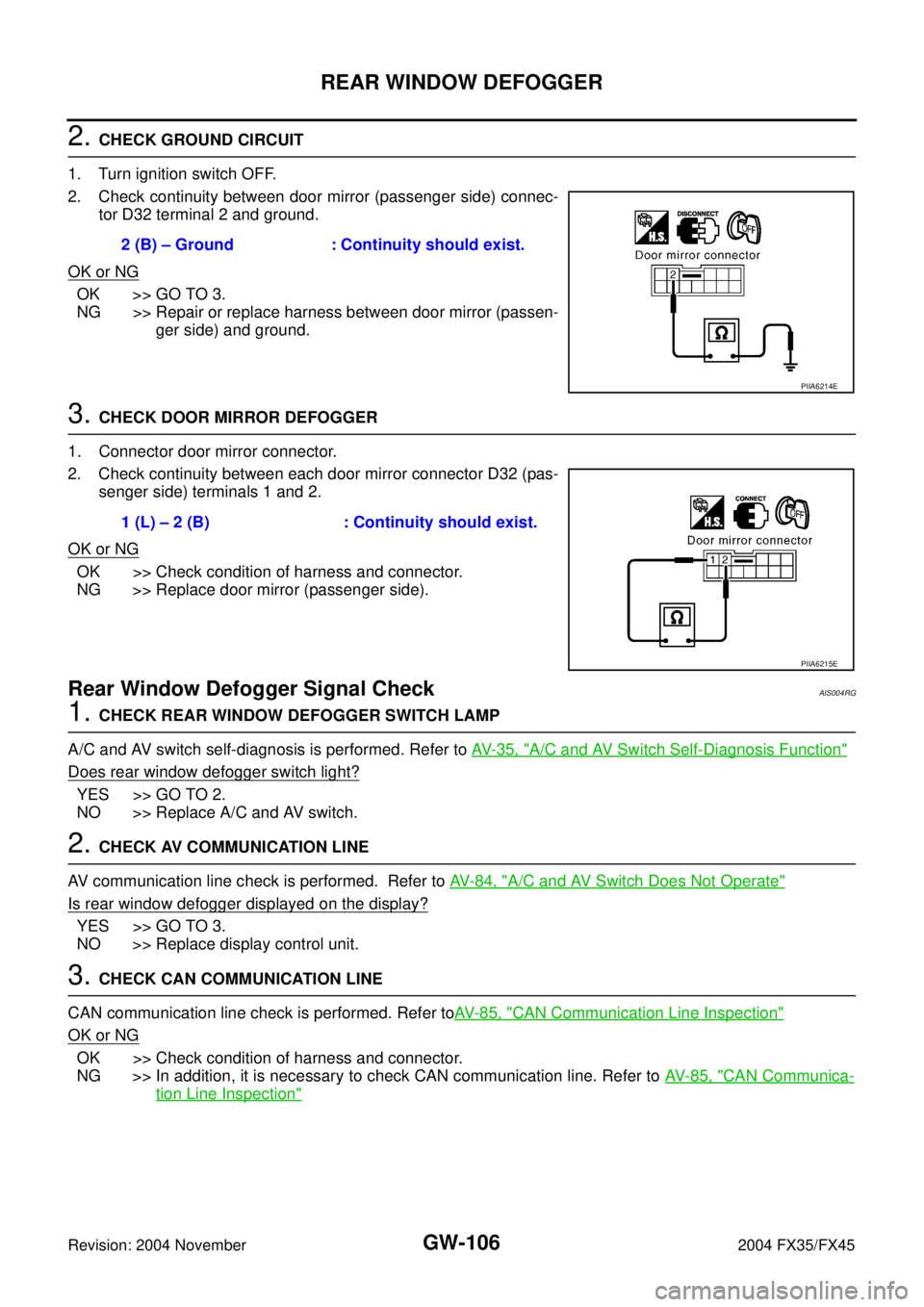
2. CHECK GROUND CIRCUIT
1. Turn ignition switch OFF.
2. Check continuity between door mirror (passenger side) connec-
tor D32 terminal 2 and ground.
OK or NG
OK >> GO TO 3.
NG >> Repair or replace harness between door mirror (passen-
ger side) and ground.
3. CHECK DOOR MIRROR DEFOGGER
1. Connector door mirror connector.
2. Check continuity between each door mirror connector D32 (pas-
senger side) terminals 1 and 2.
OK or NG
OK >> Check condition of harness and connector.
NG >> Replace door mirror (passenger side).
Rear Window Defogger Signal CheckAIS004RG
1. CHECK REAR WINDOW DEFOGGER SWITCH LAMP
A/C and AV switch self-diagnosis is performed. Refer to AV- 3 5 , "
A/C and AV Switch Self-Diagnosis Function"
Does rear window defogger switch light?
YES >> GO TO 2.
NO >> Replace A/C and AV switch.
2. CHECK AV COMMUNICATION LINE
AV communication line check is performed. Refer to AV- 8 4 , "
A/C and AV Switch Does Not Operate"
Is rear window defogger displayed on the display?
YES >> GO TO 3.
NO >> Replace display control unit.
3. CHECK CAN COMMUNICATION LINE
CAN communication line check is performed. Refer toAV- 8 5 , "
CAN Communication Line Inspection"
OK or NG
OK >> Check condition of harness and connector.
NG >> In addition, it is necessary to check CAN communication line. Refer to AV- 8 5 , "
CAN Communica-
tion Line Inspection"
2 (B) – Ground : Continuity should exist.
PIIA6214E
1 (L) – 2 (B) : Continuity should exist.
PIIA6215E
Page 3279 of 4449
IDX-6
ALPHABETICAL INDEX
M
M/ANT - Wiring diagram .................................... AV-50
MAFS - Wiring diagram ..... EC-168, EC-175, EC-825,
EC-832
, EC-1066
Magnet clutch ................................. ATC-84, ATC-143
MAIN - Wiring diagram ...................... EC-136, EC-785
Maintenance (engine)(VQ35DE) ...................... MA-14
Major overhaul (Final drive) ............................ RFD-14
Major overhaul (Transfer) .................................. TF-45
Mass air flow sensor (MAFS) ............ EC-165, EC-173,
EC-822
, EC-830, EC-1064
Meter ..................................................................... DI-4
METER - Wiring diagram ...................................... DI-9
MIL data link connectors circuit ....... EC-641, EC-1318
MIL/DL - Wiring diagram .................. EC-641, EC-1318
Mirror, door ..................................................... GW-113
Mirror, out side ................................................ GW-113
Misfire ................................................ EC-291, EC-949
Mode door control linkage adjustment ............. ATC-72
Mode door motor ............................ ATC-70, ATC-130
Molding - See Exterior ................... EI-26, EI-30, EI-33
Multiport fuel injection (MFI) system .... EC-32, EC-679
Multiport fuel injection precautions ....................... GI-7
N
NATS - Wiring diagram .................................... BL-209
NAVI - Wiring diagram ..................................... AV-107
Navigation system ............................................. AV-88
Nissan torque demand (NTD) control system .. EC-682
NVH troubleshooting (EM) .............................. EM-166
NVH troubleshooting (EM)(VQ35DE) ............... EM-13
NVH troubleshooting (Transfer) ........................... TF-7
NVIS (Nissan vehicle immobilizer system) precautions
GI-3
O
O2H1B1 - Wiring diagram .................. EC-151
, EC-808
O2H1B2 - Wiring diagram .................. EC-153, EC-810
O2H2B1 - Wiring diagram .................. EC-159, EC-816
O2H2B2 - Wiring diagram .................. EC-161, EC-818
O2S1B1 - Wiring diagram .. EC-207, EC-217, EC-229,
EC-865
, EC-875, EC-887
O2S1B2 - Wiring diagram .. EC-209, EC-219, EC-231,
EC-867
, EC-877, EC-889
O2S2B1 - Wiring diagram .. EC-238, EC-248, EC-449,
EC-460
, EC-896, EC-906, EC-1119, EC-1130
O2S2B2 - Wiring diagram .. EC-240, EC-250, EC-451,
EC-462
, EC-898, EC-908, EC-1121, EC-1132
Oil cooler (engine)(VQ35DE) ............................. LU-14
Oil filter(VK45DE) .............................................. LU-28
Oil filter(VQ35DE) .............................................. LU-10
Oil pan (engine)(VK45DE) .............................. EM-181
Oil pan (engine)(VQ35DE) ................................ EM-30
Oil pressure (engine)(VK45DE) ......................... LU-25
Oil pressure (engine)(VQ35DE) ........................... LU-8
Oil pressure relief valve (engine)(VQ35DE) ........ LU-6
Oil pump (A/T) ................................................. AT-303
Oil pump (engine)(VK45DE) .............................. LU-31
Oil pump (engine)(VQ35DE) .............................. LU-17
Oil pump regulator valve (engine)(VK45DE) ...... LU-31
Oil pump regulator valve (engine)(VQ35DE) ..... LU-17
Oil seal replacement (engine)(VK45DE) ......... EM-221
Oil seal replacement (engine)(VQ35DE) .......... EM-94
Oil seal replacement (front of final drive) FFD-7, RFD-7
Oil seal replacement (side of final drive) FFD-9, RFD-9
ORVR (On-board Refueling Vapor Recovery) EC-650,
EC-1327
Out side mirror ............................................... GW-113
Overheat ........................................................ EC-1142
P
P/SCKT - Wiring diagram ................................ WW-54
Park/Neutral position switch ........... EC-545, EC-1211
Park/neutral position switch (A/T) .................... AT-112
Parking brake control ........................................... PB-3
PCV (positive crankcase ventilation) EC-655, EC-1332
Personal lamp ..................................... LT-151, LT-184
PGC/V - Wiring diagram .... EC-337, EC-496, EC-992,
EC-1162
PHSB1 - Wiring diagram .................................. EC-309
PHSB2 - Wiring diagram .................................. EC-311
Pilot bushing replacement - See Pilot
converter(VQ35DE) ........................................ EM-121
Piston assembly(VK45DE) ............................. EM-250
Piston assembly(VQ35DE) ............................. EM-131
Piston pin inspection(VK45DE) ....................... EM-256
Piston pin inspection(VQ35DE) ...................... EM-136
Piston ring inspection(VK45DE) ..................... EM-257
Piston ring inspection(VQ35DE) ..................... EM-137
Piston to bore clearance(VK45DE) ................. EM-260
Piston to bore clearance(VQ35DE) ................ EM-140
PNP/SW - Wiring diagram .............. EC-547, EC-1213
POS - Wiring diagram ....................... EC-303, EC-961
POWER - Wiring diagram ................................... PG-4
Power door mirror .............................................. BL-22
Power seat ......................................................... SE-93
Power socket ................................................... WW-54
Power steering fluid level ........................ PS-8, MA-36
Power steering gear ........................................... PS-19
Power steering hydraulic pressure .................... PS-31
Power steering oil pump .................................... PS-31
Power steering system bleeding .......................... PS-8
Power supply routing .......................................... PG-3
Power window .................................................. GW-15
PRE/SE - Wiring diagram EC-354, EC-360, EC-1009,
EC-1016
Precations for Leak detection dye .................. ATC-16
Precautions (General) ........................................... GI-4
Pressure switch 1 .............................. AT-158, AT-178
Pressure switch 2 ............................................ AT-170
Pressure switch 3 .............................. AT-154, AT-180
Pressure switch 5 .............................. AT-162, AT-182
Pressure switch 6 .............................. AT-166, AT-184
Pressure test (A/T) ............................................. AT-52
Page 3280 of 4449
IDX-7
A
C
D
E
F
G
H
I
J
K
L B
IDX
ALPHABETICAL INDEX
Propeller shaft ..................................................... PR-6
Propeller shaft on vehicle service ........................ PR-6
Propeller shaft vibration ....................................... PR-6
PS/SEN - Wiring diagram ................ EC-397, EC-1053
R
R/VIEW - Wiring diagram ................................... DI-84
Radiator(VK45DE) ............................................. CO-39
Radiator(VQ35DE) ............................................ CO-14
Rear axle ........................................................... RAX-5
Rear bumper ........................................................ EI-18
Rear combination lamp removal and installation ..........
LT-147
Rear door ............................................ BL-148, GW-80
Rear seat ......................................................... SE-107
Rear suspension ............................................... RSU-5
Rear view monitor ............................................... DI-81
Rear washer .................................................... WW-35
Rear window defogger ...................................... GW-86
Rear wiper ....................................................... WW-35
Refrigerant connection precaution ..................... ATC-8
Refrigerant discharging evacuating charging ATC-137
Refrigerant general precaution .......................... ATC-7
Refrigerant lines ............................................ ATC-137
Refrigerant pressure sensor ........... EC-609, EC-1287,
ATC-90
, ATC-155
Refrigeration cycle ........................................... ATC-21
Removal and installation (A/T) ........... AT-266, AT-269
Removal and installation (Transfer) .................... TF-43
Revolution sensor (A/T) ...................... AT-116, AT-260
Ring gear diff. inspection ................................. RFD-13
Rocker cover(VK45DE) ................................... EM-193
Rocker cover(VQ35DE) ..................................... EM-51
Room lamp - See Interior lamp ......................... LT-157
ROOM/L - Wiring diagram ................................ LT-164
RP/SEN - Wiring diagram ................ EC-610, EC-1288
S
Seal - See Exterior .............................................. EI-28
SEAT - Wiring diagram ...................................... SE-95
Seat belt inspection ............................................. SB-8
Seat belt pre-tensioner disposal ...................... SRS-49
Seat belt, front ..................................................... SB-4
Seat, rear ......................................................... SE-107
Self-diagnosis (Transfer) .................................... TF-21
SEN/PW - Wiring diagram ............... EC-490, EC-1157
SHIFT - Wiring diagram ................................... AT-236
Shift change signal ........................................ EC-1218
Shift lock system .............................................. AT-235
Shift schedule .................................................. AT-348
Shock absorber (rear) ....................................... RSU-9
Side air bag (satellite) sensor .......................... SRS-46
Side bearing preload diff. ................................. RFD-20
Side curtain air bag .......................................... SRS-43
Side flange installation diff. .............................. RFD-10
Side trim .............................................................. EI-37
SMJ (super multiple junction) ............................ PG-79
Spark plug replacement .................................... MA-26
Spark plug replacement(VQ35DE) ................... MA-19
Spark plug(VK45DE) ...................................... EM-186
Spark plug(VQ35DE) ........................................ EM-43
Specification value ............................. EC-131, EC-780
Speedometer ........................................................ DI-4
Spiral cable ..................................................... SRS-38
Spot lamp .......................................................... LT-184
SROOF - Wiring diagram ..................... BL-167, RF-14
SRS - See Supplemental Restraint System ..... SRS-5
SRS Trouble diagnoses .................................... SRS-7
Stabilizer bar (rear) ......................................... RSU-16
Stall test (A/T) .................................................... AT-51
Standardized relay ............................................. PG-81
START - Wiring diagram .................................... SC-11
Starter ................................................................ SC-10
Starting system .................................................. SC-10
Steering gear and linkage inspection ................ MA-35
Steering linkage ................................................. PS-19
Steering wheel and column ................... PS-10, PS-12
Steering wheel turning force .............................. PS-10
Step lamp .......................................................... LT-124
Stop lamp .......................................................... LT-116
Stop lamp switch .............................. EC-550, EC-1220
STOP/L - Wiring diagram .................................. LT-118
Sun roof, electric ................................................ RF-10
Sunload sensor ............................. ATC-110, ATC-119
Sunroof .................................................. RF-10, RF-25
Supplemental Restraint System ....................... SRS-5
Suspension ....................................................... MA-36
Symbols and abbreviations ...................... GI-10, GI-23
T
Tachometer ........................................................... DI-4
TCM circuit diagram ........................................... AT-50
TCM inspection table ......................................... AT-90
Thermostat(VK45DE) ....................................... CO-51
Thermostat(VQ35DE) ....................................... CO-26
Three way catalyst function (Bank 1) . EC-316, EC-971
Three way catalyst function (Bank 2) . EC-316, EC-971
Three way catalyst precautions ............................ GI-6
Three way catalyst(VK45DE) .......................... EM-178
Three way catalyst(VQ35DE) ........................... EM-26
Throttle control motor ....................... EC-428, EC-1090
Throttle control motor relay .............. EC-423, EC-1085
Throttle position sensor (TPS) .......... EC-190, EC-284,
EC-485
, EC-487, EC-569, EC-848, EC-942, EC-1152,
EC-1154
, EC-1239
Tie-rod ............................................................... PS-19
Timing chain(VK45DE) ................................... EM-196
Timing chain(VQ35DE) ..................................... EM-63
Tire rotation ............................................. WT-6, MA-34
Tooth contact diff. ........................................... RFD-24
Top tether strap child restraint ........................... SB-12
Torque converter installation AT-267, AT-268, AT-272
Torque convertor clutch solenoid valve AT-123, AT-125
TPS1 - Wiring diagram ...................... EC-286, EC-944
TPS2 - Wiring diagram ...................... EC-192, EC-850
Page 3281 of 4449
IDX-8
ALPHABETICAL INDEX
TPS3 - Wiring diagram .................... EC-571, EC-1241
Transfer control unit inspection table ................. TF-19
Transverse link (front) ...................................... FSU-14
TRNSCV - Wiring diagram ............................... BL-228
Trouble diagnoses .............................................. GI-11
Turbine revolution sensor ................................ AT-143
TURN - Wiring diagram ...................................... LT-94
Turn signal lamp ................................................. LT-89
Tyre pressure monitoring system - trouble diagnoses ..
WT-10
Tyre pressure monitoring system - wiring diagram .......
WT-11
U
Unified meter and A/C amp. ............................... DI-28
V
Vacuum hose (brake system) ............................ BR-18
Vacuum hose drawing (Engine control) ............. EC-30
Valve clearance(VK45DE) .............................. EM-214
Valve clearance(VQ35DE) ................................ EM-89
Valve guide ..................................................... EM-105
Valve guide(VK45DE) ..................................... EM-231
Valve lifter(VK45DE) ....................................... EM-211
Valve lifter(VQ35DE) ........................................ EM-86
Valve seat(VK45DE) ......................... EM-232, EM-233
Valve seat(VQ35DE) ...................................... EM-107
Valve spring(VK45DE) ...................... EM-234, EM-235
Valve spring(VQ35DE) ................................... EM-108
Vanity mirror lamp ............................................. LT-149
Variable induction air control system (VIAS) . EC-1254
VDC -Wiring diagram ...................................... BRC-17
Vehicle security (theft warning) system ........... BL-181
Vehicle speed sensor (VSS) ........... EC-390, EC-1046,
EC-1216
VEHSEC - Wiring diagram ............................... BL-187
VENT/V - Wiring diagram .. EC-344, EC-504, EC-999,
EC-1170
VIAS - Wiring diagram ................................... EC-1256
W
WARN - Wiring diagram ..................................... DI-40
Warning chime .................................................... DI-55
Warning lamps .................................................... DI-39
Washer, front ..................................................... WW-4
Washer, rear .................................................... WW-35
Water control valve(VK45DE) ........................... CO-51
Water pump(VK45DE) ...................................... CO-49
Water pump(VQ35DE) ...................................... CO-22
Water temperature gauge ..................................... DI-4
Wheel alignment (front) ..................................... FSU-6
Wheel alignment (rear) ..................................... RSU-5
Wheel balance ........................................ WT-5, MA-32
Wheel bearing (front) ........................... FAX-4, FAX-10
Wheel bearing (rear) ......................................... RAX-5
Wheel hub (front) ................................. FAX-4, FAX-10
Wheel hub (rear) ............................................... RAX-5
Wheel sensor (VDC) ....................................... BRC-57
WINDOW - Wiring diagram .............................. GW-24
Window, door ...................................... GW-76, GW-80
Windshield ....................................................... GW-11
WIP/R - Wiring diagram ................................... WW-37
WIPER - Wiring diagram .................................. WW-11
Wiper, front ........................................................ WW-4
Wiper, rear ....................................................... WW-35
Wiring Diagram (Cell code) list ......................... PG-67
Wiring diagrams .................................................. GI-15
WT-T/WARN - Wiring diagram .......................... WT-11
Page 3309 of 4449
![INFINITI FX35 2004 Service Manual LAN-8
[CAN]
CAN COMMUNICATION
Revision: 2004 November 2004 FX35/FX45
Position light request signal R T R R
Low beam request signal T R
Low beam status signal RT
High beam request signal T R R
High bea INFINITI FX35 2004 Service Manual LAN-8
[CAN]
CAN COMMUNICATION
Revision: 2004 November 2004 FX35/FX45
Position light request signal R T R R
Low beam request signal T R
Low beam status signal RT
High beam request signal T R R
High bea](/manual-img/42/57021/w960_57021-3308.png)
LAN-8
[CAN]
CAN COMMUNICATION
Revision: 2004 November 2004 FX35/FX45
Position light request signal R T R R
Low beam request signal T R
Low beam status signal RT
High beam request signal T R R
High beam status signal RT
Front fog light request signal T R
Day time running light request signal T R
Turn LED burnout status signal R T
Vehicle speed signalRT
RRRR T R
Sleep wake up signal T R R
Door switch signal R T R R R
Turn indicator signal T R
Key fob ID signal T R
Key fob door unlock signal T R
Oil pressure switch signalRT
TR
Buzzer output signal T R
Fuel level sensor signal R T
Fuel level low warning signal R T
ASCD SET lamp signal T R
ASCD CRUISE lamp signal T R
Malfunction indicator lamp signal T R
ASCD operation signal T R
ASCD OD cancel request signal T R
Front wiper request signal T R
Front wiper stop position signal R T
Rear window defogger switch signal T R
Rear window defogger control signal R R R T
Hood switch signal R T
Theft warning horn request signal T R
Horn chirp signal T R
Steering angle sensor signal T R
ABS warning lamp signalRT
VDC OFF indicator lamp signal R T
SLIP indicator lamp signalRT
Brake warning lamp signal R T
System setting signalTR R
RT T
A/T CHECK indicator lamp signal T RSignals ECM TCMDis-
play
unitBCMSteer-
ing
angle
sensorUnified
meter
and
A/C
amp.ABS
actua-
tor and
electric
unit
(con-
trol
unit)Driver
seat
control
unitIPDM
E/R