Page 2791 of 4449
![INFINITI FX35 2004 Service Manual EM-66
[VQ35DE]
TIMING CHAIN
Revision: 2004 November 2004 FX35/FX45
b. Loosen crankshaft pulley bolt and locate bolt seating surface as
10 mm (0.39 in) from its original position.
CAUTION:
Do not remov](/manual-img/42/57021/w960_57021-2790.png "INFINITI FX35 2004 Service Manual EM-66
[VQ35DE]
TIMING CHAIN
Revision: 2004 November 2004 FX35/FX45
b. Loosen crankshaft pulley bolt and locate bolt seating surface as
10 mm (0.39 in) from its original position.
CAUTION:
Do not remov")
EM-66
[VQ35DE]
TIMING CHAIN
Revision: 2004 November 2004 FX35/FX45
b. Loosen crankshaft pulley bolt and locate bolt seating surface as
10 mm (0.39 in) from its original position.
CAUTION:
Do not remove crankshaft pulley bolt as it will be used as a
supporting point for suitable puller.
c. Place suitable puller tab on holes of crankshaft pulley, and pull
crankshaft pulley through.
CAUTION:
Do not put suitable puller tab on crankshaft pulley periph-
ery, as this will damage internal damper.
22. Remove oil pan (upper and lower). Refer to EM-30, "
OIL PAN AND OIL STRAINER" .
23. Remove front timing chain case.
a. Loosen mounting bolts with power tool in reverse order as
shown in the figure.
b. Insert suitable tool into the notch at the top of front timing chain
case as shown (1) in the figure.
c. Pry off case by moving tool as shown (2) in the figure.
�U s e s e a l c u t t e r [ S S T: K V 1 0 1111 0 0 ( J - 3 7 2 2 8 ) ] o r a n e q u i v a l e n t
tool to cut liquid gasket for removal.
CAUTION:
�Do not use screwdrivers or something similar.
�After removal, handle it carefully so it does not tilt,
cant, or warp under a load.
PBIC1103E
EMQ0477D
KBIA1303E
SEM156F
Page 2792 of 4449
![INFINITI FX35 2004 Service Manual TIMING CHAIN
EM-67
[VQ35DE]
C
D
E
F
G
H
I
J
K
L
MA
EM
Revision: 2004 November 2004 FX35/FX45
24. Remove O-rings from rear timing chain case.
25. Remove water pump cover and chain tensioner cover from](/manual-img/42/57021/w960_57021-2791.png "INFINITI FX35 2004 Service Manual TIMING CHAIN
EM-67
[VQ35DE]
C
D
E
F
G
H
I
J
K
L
MA
EM
Revision: 2004 November 2004 FX35/FX45
24. Remove O-rings from rear timing chain case.
25. Remove water pump cover and chain tensioner cover from")
TIMING CHAIN
EM-67
[VQ35DE]
C
D
E
F
G
H
I
J
K
L
MA
EM
Revision: 2004 November 2004 FX35/FX45
24. Remove O-rings from rear timing chain case.
25. Remove water pump cover and chain tensioner cover from front timing chain case.
�U s e s e a l c u t t e r [ S S T: K V 1 0 1111 0 0 ( J - 3 7 2 2 8 ) ] o r a n e q u i v a l e n t t o o l t o c u t l i q u i d g a s k e t f o r r e m o v a l .
26. Remove front oil seal from front timing chain case using a suit-
able tool.
�Use screwdriver for removal.
CAUTION:
Be careful not to damage front timing chain case.
27. Remove timing chain tensioner (primary) as the following:
a. Pull lever down and release plunger stopper tab.
�Plunger stopper tab can be pushed up to release (coaxial
structure with lever).
b. Insert stopper pin into tensioner body hole to hold lever, and
keep the tab released.
NOTE:
An Allen wrench [2.5 mm (0.098 in)] is used for a stopper pin as
an example.
c. Insert plunger into tensioner body by pressing slack guide.
d. Keep slack guide pressed and hold it by pushing stopper pin
through the lever hole and body hole.
e. Remove mounting bolts and remove timing chain tensioner (pri-
mary).
SBIA0497E
EMQ0032D
PBIC2107E
SEM733G
Page 2793 of 4449
![INFINITI FX35 2004 Service Manual EM-68
[VQ35DE]
TIMING CHAIN
Revision: 2004 November 2004 FX35/FX45
28. Remove internal chain guide, tension guide and slack guide.
NOTE:
Tension guide can be removed after removing timing chain (pri-](/manual-img/42/57021/w960_57021-2792.png "INFINITI FX35 2004 Service Manual EM-68
[VQ35DE]
TIMING CHAIN
Revision: 2004 November 2004 FX35/FX45
28. Remove internal chain guide, tension guide and slack guide.
NOTE:
Tension guide can be removed after removing timing chain (pri-")
EM-68
[VQ35DE]
TIMING CHAIN
Revision: 2004 November 2004 FX35/FX45
28. Remove internal chain guide, tension guide and slack guide.
NOTE:
Tension guide can be removed after removing timing chain (pri-
mary).
29. Remove timing chain (primary), tension guide and crankshaft sprocket.
CAUTION:
After removing timing chain, do not turn crankshaft and camshaft separately, or valves will strike
piston heads.
30. Remove timing chain (secondary) and camshaft sprockets as the following:
a. Attach a suitable stopper pin to right and left camshaft chain ten-
sioners (for secondary timing chains).
NOTE:
For removal and installation of secondary chain tensioner, refer
to EM-82, "
CAMSHAFT" . (Removing No. 1 camshaft bracket is
required.)
b. Remove intake and exhaust camshaft sprocket bolts.
�Apply paint to timing chain and camshaft sprockets for align-
ment during installation.
�Secure the hexagonal portion of camshaft using a wrench to
loosen mounting bolts.
c. Remove timing chain (secondary) together with camshaft sprockets.
�Turn camshaft slightly to secure slackness of timing chain on timing chain tensioner (secondary) side.
PBIC2266E
SEM923G
KBIA1698J
Page 2794 of 4449
![INFINITI FX35 2004 Service Manual TIMING CHAIN
EM-69
[VQ35DE]
C
D
E
F
G
H
I
J
K
L
MA
EM
Revision: 2004 November 2004 FX35/FX45
�Insert 0.5 mm (0.020 in)-thick metal or resin plate between
timing chain and timing chain tensioner plunge](/manual-img/42/57021/w960_57021-2793.png "INFINITI FX35 2004 Service Manual TIMING CHAIN
EM-69
[VQ35DE]
C
D
E
F
G
H
I
J
K
L
MA
EM
Revision: 2004 November 2004 FX35/FX45
�Insert 0.5 mm (0.020 in)-thick metal or resin plate between
timing chain and timing chain tensioner plunge")
TIMING CHAIN
EM-69
[VQ35DE]
C
D
E
F
G
H
I
J
K
L
MA
EM
Revision: 2004 November 2004 FX35/FX45
�Insert 0.5 mm (0.020 in)-thick metal or resin plate between
timing chain and timing chain tensioner plunger (guide).
Remove timing chain (secondary) together with camshaft
sprockets with timing chain loose from guide groove.
CAUTION:
Be careful of plunger coming-off when removing timing
chain (secondary). This is because plunger of timing
chain tensioner (secondary) moves during operation,
leading to coming-off of fixed stopper pin.
NOTE:
Camshaft sprocket (INT) is two-for-one structure of primary
and secondary sprockets.
�When handling camshaft sprocket (INT), be careful of the fol-
lowing:
CAUTION:
�Handle carefully to avoid any shock to camshaft
sprocket.
�Do not disassemble. (Do not loosen bolts “A” and “B”
as shown in the figure).
31. Remove rear timing chain case as follows:
a. Loosen and remove mounting bolts in reverse order as shown in
the figure.
b . C u t s e a l a n t u s i n g a s e a l c u t t e r [ S S T: K V 1 0 1111 0 0 ( J - 3 7 2 2 8 ) ] o r
an equivalent tool and remove rear timing chain case.
CAUTION:
�Do not remove plate metal cover of engine oil passage.
�After removing chain case, do not apply any load which
affects flatness.
PBIC1978E
SEM734G
SEM735G
KBIA1307E
Page 2795 of 4449
EM-70
[VQ35DE]
TIMING CHAIN
Revision: 2004 November 2004 FX35/FX45
32. Remove O-rings from cylinder head.
33. Remove O-rings from cylinder block.
34. Remove timing chain tensioners (secondary) from cylinder head as the following, if necessary.
a. Remove No. 1 camshaft brackets. Refer to EM-83, "
REMOVAL" .
b. Remove timing chain tensioners (secondary) with stopper pin attached.
35. Use a scraper to remove all traces of liquid gasket from front
and rear timing chain cases, and opposite mating surfaces.
CAUTION:
Be careful not to allow gasket fragments to enter oil pan.
�Remove old liquid gasket from the bolt hole and thread.
SBIA0496E
PBIC0788E
SEM737G
PBIC2084E
Page 2796 of 4449
TIMING CHAIN
EM-71
[VQ35DE]
C
D
E
F
G
H
I
J
K
L
MA
EM
Revision: 2004 November 2004 FX35/FX45
36. Use a scraper to remove all traces of liquid gasket from water
pump cover, chain tensioner cover and intake valve timing con-
trol covers.
INSPECTION AFTER REMOVAL
Timing Chain
Check for cracks and any excessive wear at link plates and roller
links of timing chain. Replace timing chain as necessary.
INSTALLATION
NOTE:
The below figure shows the relationship between the mating mark on each timing chain and that on the corre-
sponding sprocket, with the components installed.
SEM926E
PBIC0282E
KBIA1053E
Page 2797 of 4449
EM-72
[VQ35DE]
TIMING CHAIN
Revision: 2004 November 2004 FX35/FX45
1. Install timing chain tensioners (secondary) to cylinder head as the following if removed. Refer to EM-87,
"INSTALLATION" .
a. Install chain tensioners with stopper pin attached and new O-rings.
b. Install No. 1 camshaft brackets. Refer to EM-87, "
INSTALLATION" .
2. Install new O-rings onto cylinder block.
3. Install new O-rings to cylinder head.
4. Apply liquid gasket to rear timing chain case back side as shown with tube presser [SST: WS39930000 ( –
)].
Use Genuine RTV Silicone Sealant or equivalent. Refer to GI-48, "
RECOMMENDED CHEMICAL
PRODUCTS AND SEALANTS".
CAUTION:
�For “A” in the figure, completely wipe out liquid gasket extended on a portion touching at
engine coolant.
PBIC0788E
SBIA0496E
Page 2798 of 4449
TIMING CHAIN
EM-73
[VQ35DE]
C
D
E
F
G
H
I
J
K
L
MA
EM
Revision: 2004 November 2004 FX35/FX45
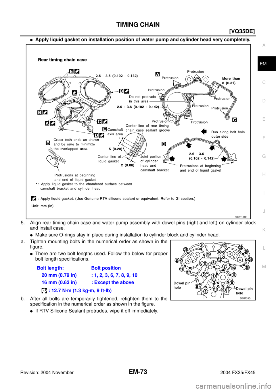
�Apply liquid gasket on installation position of water pump and cylinder head very completely.
5. Align rear timing chain case and water pump assembly with dowel pins (right and left) on cylinder block
and install case.
�Make sure O-rings stay in place during installation to cylinder block and cylinder head.
a. Tighten mounting bolts in the numerical order as shown in the
figure.
�There are two bolt lengths used. Follow the below for proper
bolt length specifications.
b. After all bolts are temporarily tightened, retighten them to the
specification in the numerical order as shown in the figure.
�If RTV Silicone Sealant protrudes, wipe it off immediately.Bolt length: Bolt position
20 mm (0.79 in) : 1, 2, 3, 6, 7, 8, 9, 10
16 mm (0.63 in) : Except the above
: 12.7 N·m (1.3 kg-m, 9 ft-lb)
PBIC1131E
SEM735G
![INFINITI FX35 2004 Service Manual EM-70
[VQ35DE]
TIMING CHAIN
Revision: 2004 November 2004 FX35/FX45
32. Remove O-rings from cylinder head.
33. Remove O-rings from cylinder block.
34. Remove timing chain tensioners (secondary) from cy](/manual-img/42/57021/w960_57021-2794.png "INFINITI FX35 2004 Service Manual EM-70
[VQ35DE]
TIMING CHAIN
Revision: 2004 November 2004 FX35/FX45
32. Remove O-rings from cylinder head.
33. Remove O-rings from cylinder block.
34. Remove timing chain tensioners (secondary) from cy")
![INFINITI FX35 2004 Service Manual TIMING CHAIN
EM-71
[VQ35DE]
C
D
E
F
G
H
I
J
K
L
MA
EM
Revision: 2004 November 2004 FX35/FX45
36. Use a scraper to remove all traces of liquid gasket from water
pump cover, chain tensioner cover and in](/manual-img/42/57021/w960_57021-2795.png "INFINITI FX35 2004 Service Manual TIMING CHAIN
EM-71
[VQ35DE]
C
D
E
F
G
H
I
J
K
L
MA
EM
Revision: 2004 November 2004 FX35/FX45
36. Use a scraper to remove all traces of liquid gasket from water
pump cover, chain tensioner cover and in")
![INFINITI FX35 2004 Service Manual EM-72
[VQ35DE]
TIMING CHAIN
Revision: 2004 November 2004 FX35/FX45
1. Install timing chain tensioners (secondary) to cylinder head as the following if removed. Refer to EM-87,
"INSTALLATION" .
a. Inst](/manual-img/42/57021/w960_57021-2796.png "INFINITI FX35 2004 Service Manual EM-72
[VQ35DE]
TIMING CHAIN
Revision: 2004 November 2004 FX35/FX45
1. Install timing chain tensioners (secondary) to cylinder head as the following if removed. Refer to EM-87,
\"INSTALLATION\" .
a. Inst")