2004 INFINITI FX35 seat
[x] Cancel search: seatPage 4188 of 4449
AUTOMATIC DRIVE POSITIONER
SE-59
C
D
E
F
G
H
J
K
L
MA
B
SE
Revision: 2004 November 2004 FX35/FX45
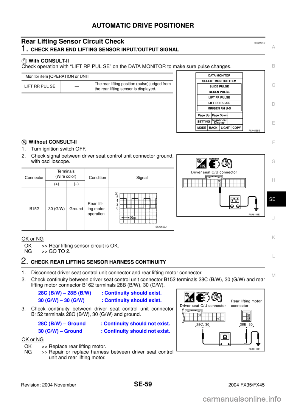
Rear Lifting Sensor Circuit CheckAIS002XV
1. CHECK REAR END LIFTING SENSOR INPUT/OUTPUT SIGNAL
With CONSULT-II
Check operation with “LIFT RP PUL SE” on the DATA MONITOR to make sure pulse changes.
Without CONSULT-II
1. Turn ignition switch OFF.
2. Check signal between driver seat control unit connector ground,
with oscilloscope.
OK or NG
OK >> Rear lifting sensor circuit is OK.
NG >> GO TO 2.
2. CHECK REAR LIFTING SENSOR HARNESS CONTINUITY
1. Disconnect driver seat control unit connector and rear lifting motor connector.
2. Check continuity between driver seat control unit connector B152 terminals 28C (B/W), 30 (G/W) and rear
lifting motor connector B162 terminals 28B (B/W), 30 (G/W).
3. Check continuity between driver seat control unit connector
B152 terminals 28C (B/W), 30 (G/W) and ground.
OK or NG
OK >> Replace rear lifting motor.
NG >> Repair or replace harness between driver seat control
unit and rear lifting motor.
Monitor item [OPERATION or UNIT
LIFT RR PUL SE —The rear lifting position (pulse) judged from
the rear lifting sensor is displayed.
PIIA4558E
ConnectorTe r m i n a l s
(Wire color)
Condition Signal
(+) (–)
B152 30 (G/W) GroundRear lift-
ing motor
operation
P I I A 6 111 E
SIIA0693J
28C (B/W) – 28B (B/W) : Continuity should exist.
30 (G/W) – 30 (G/W) : Continuity should exist.
28C (B/W) – Ground : Continuity should not exist.
30 (G/W) – Ground : Continuity should not exist.
PIIA6112E
Page 4196 of 4449
AUTOMATIC DRIVE POSITIONER
SE-67
C
D
E
F
G
H
J
K
L
MA
B
SE
Revision: 2004 November 2004 FX35/FX45
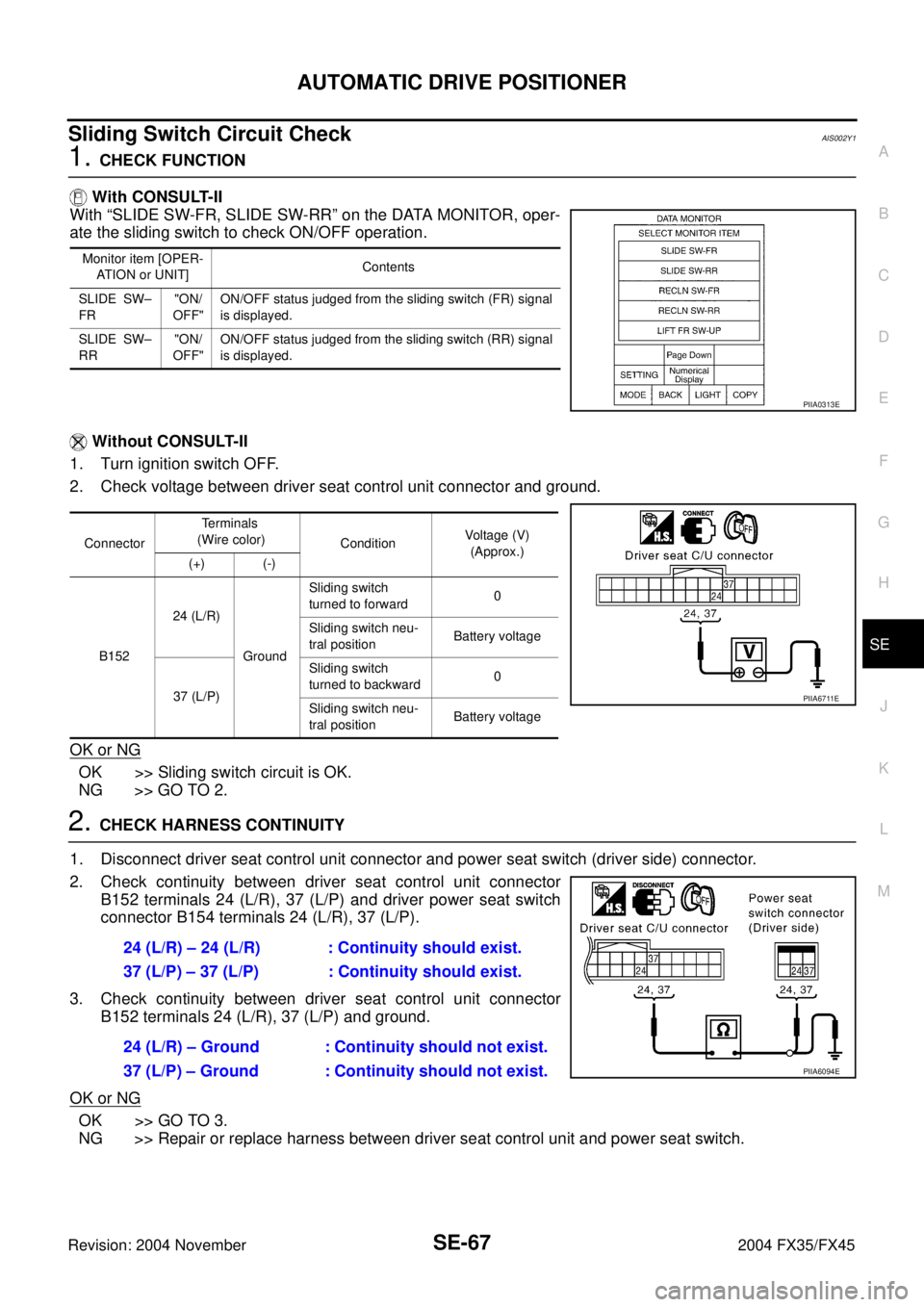
Sliding Switch Circuit CheckAIS002Y1
1. CHECK FUNCTION
With CONSULT-II
With “SLIDE SW-FR, SLIDE SW-RR” on the DATA MONITOR, oper-
ate the sliding switch to check ON/OFF operation.
Without CONSULT-II
1. Turn ignition switch OFF.
2. Check voltage between driver seat control unit connector and ground.
OK or NG
OK >> Sliding switch circuit is OK.
NG >> GO TO 2.
2. CHECK HARNESS CONTINUITY
1. Disconnect driver seat control unit connector and power seat switch (driver side) connector.
2. Check continuity between driver seat control unit connector
B152 terminals 24 (L/R), 37 (L/P) and driver power seat switch
connector B154 terminals 24 (L/R), 37 (L/P).
3. Check continuity between driver seat control unit connector
B152 terminals 24 (L/R), 37 (L/P) and ground.
OK or NG
OK >> GO TO 3.
NG >> Repair or replace harness between driver seat control unit and power seat switch.
Monitor item [OPER-
ATION or UNIT]Contents
SLIDE SW–
FR"ON/
OFF"ON/OFF status judged from the sliding switch (FR) signal
is displayed.
SLIDE SW–
RR"ON/
OFF"ON/OFF status judged from the sliding switch (RR) signal
is displayed.
PIIA0313E
ConnectorTe r m i n a l s
(Wire color)
ConditionVoltage (V)
(Approx.)
(+) (-)
B15224 (L/R)
GroundSliding switch
turned to forward0
Sliding switch neu-
tral positionBattery voltage
37 (L/P)Sliding switch
turned to backward0
Sliding switch neu-
tral positionBattery voltage
PIIA6711E
24 (L/R) – 24 (L/R) : Continuity should exist.
37 (L/P) – 37 (L/P) : Continuity should exist.
24 (L/R) – Ground : Continuity should not exist.
37 (L/P) – Ground : Continuity should not exist.
PIIA6094E
Page 4197 of 4449
SE-68
AUTOMATIC DRIVE POSITIONER
Revision: 2004 November 2004 FX35/FX45
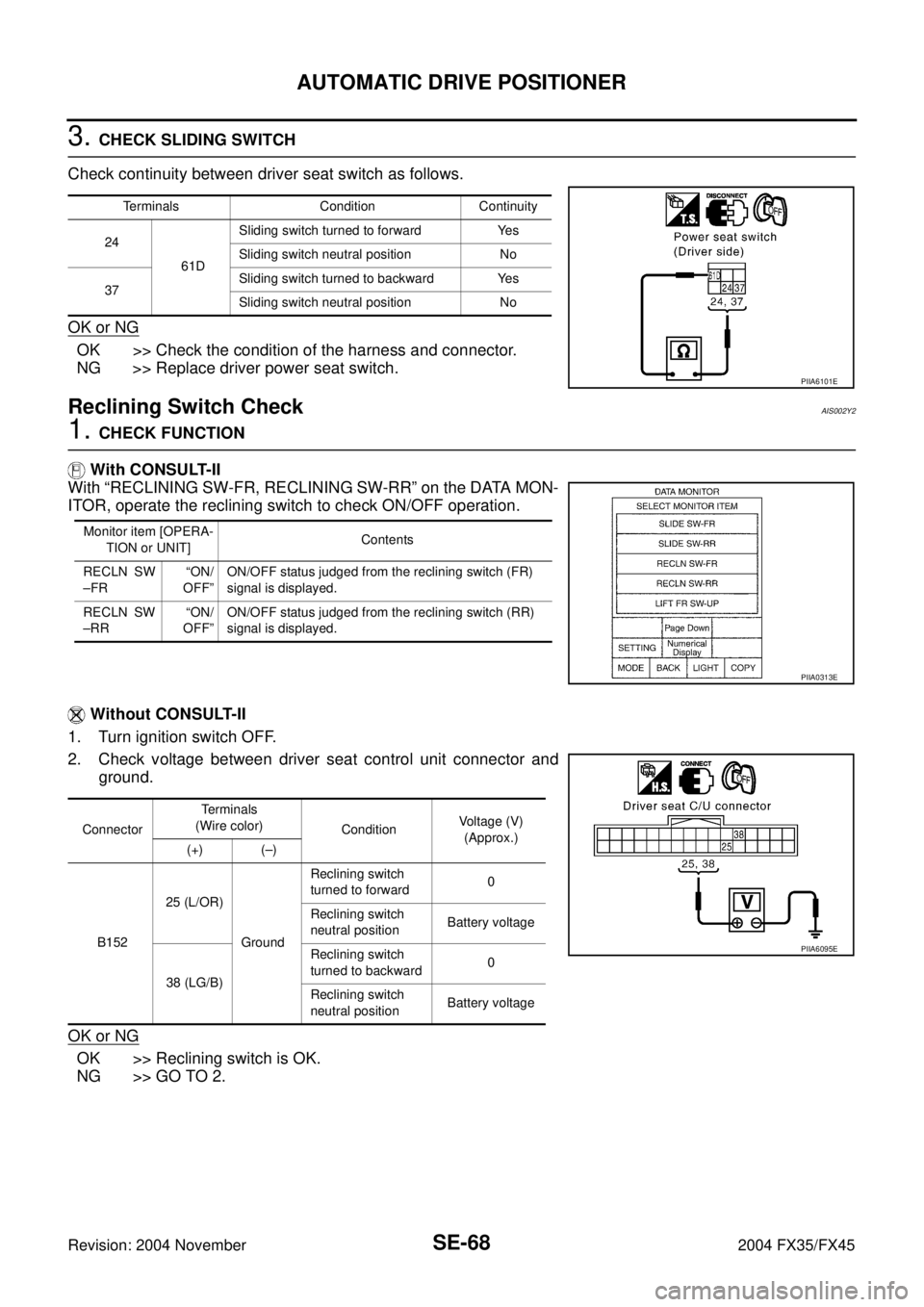
3. CHECK SLIDING SWITCH
Check continuity between driver seat switch as follows.
OK or NG
OK >> Check the condition of the harness and connector.
NG >> Replace driver power seat switch.
Reclining Switch CheckAIS002Y2
1. CHECK FUNCTION
With CONSULT-II
With “RECLINING SW-FR, RECLINING SW-RR” on the DATA MON-
ITOR, operate the reclining switch to check ON/OFF operation.
Without CONSULT-II
1. Turn ignition switch OFF.
2. Check voltage between driver seat control unit connector and
ground.
OK or NG
OK >> Reclining switch is OK.
NG >> GO TO 2.
Terminals Condition Continuity
24
61DSliding switch turned to forward Yes
Sliding switch neutral position No
37Sliding switch turned to backward Yes
Sliding switch neutral position No
PIIA6101E
Monitor item [OPERA-
TION or UNIT]Contents
RECLN SW
–FR“ON/
OFF”ON/OFF status judged from the reclining switch (FR)
signal is displayed.
RECLN SW
–RR“ON/
OFF”ON/OFF status judged from the reclining switch (RR)
signal is displayed.
PIIA0313E
ConnectorTe r m i n a l s
(Wire color)
ConditionVoltage (V)
(Approx.)
(+) (–)
B15225 (L/OR)
GroundReclining switch
turned to forward0
Reclining switch
neutral positionBattery voltage
38 (LG/B)Reclining switch
turned to backward0
Reclining switch
neutral positionBattery voltage
PIIA6095E
Page 4198 of 4449
AUTOMATIC DRIVE POSITIONER
SE-69
C
D
E
F
G
H
J
K
L
MA
B
SE
Revision: 2004 November 2004 FX35/FX45
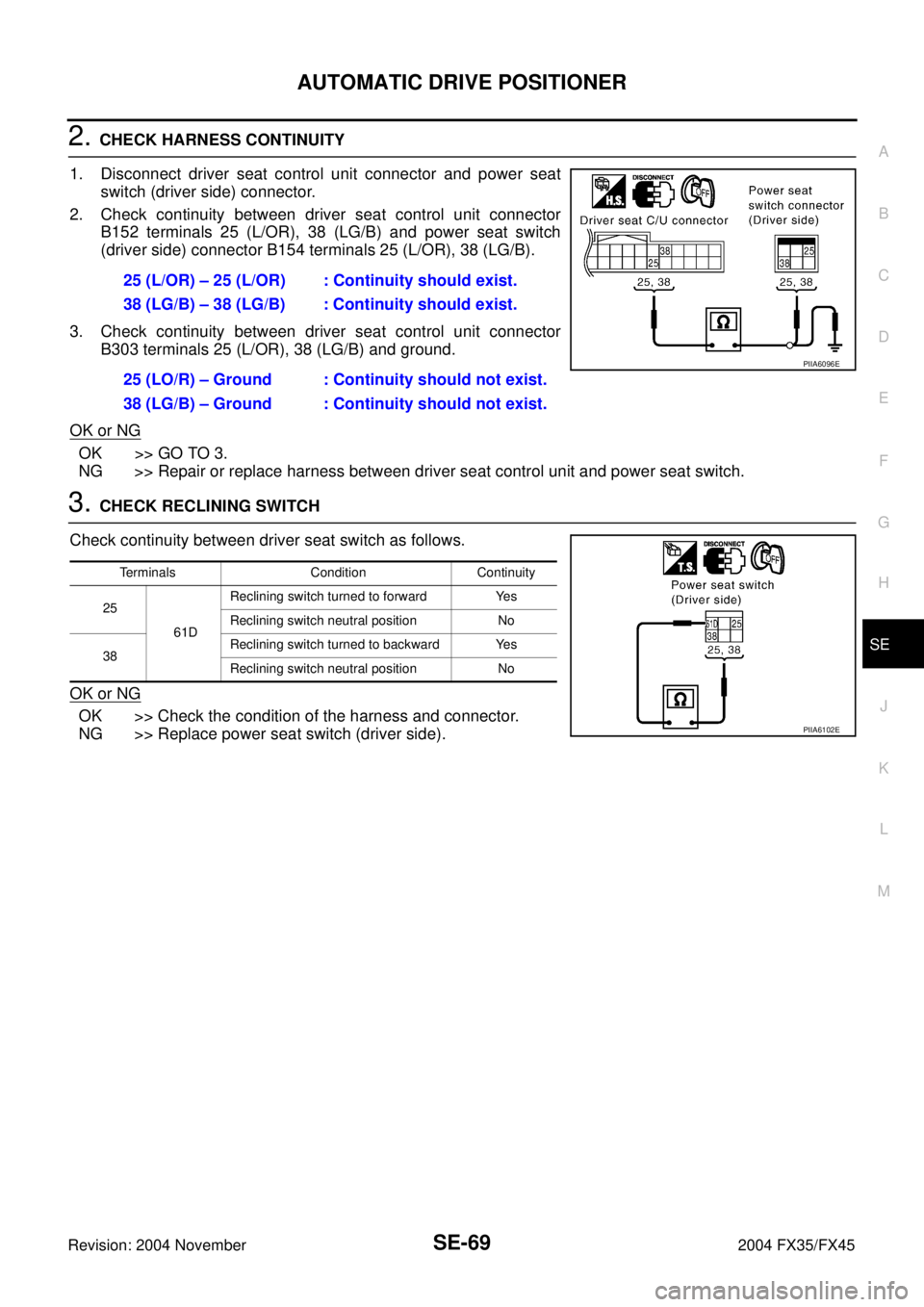
2. CHECK HARNESS CONTINUITY
1. Disconnect driver seat control unit connector and power seat
switch (driver side) connector.
2. Check continuity between driver seat control unit connector
B152 terminals 25 (L/OR), 38 (LG/B) and power seat switch
(driver side) connector B154 terminals 25 (L/OR), 38 (LG/B).
3. Check continuity between driver seat control unit connector
B303 terminals 25 (L/OR), 38 (LG/B) and ground.
OK or NG
OK >> GO TO 3.
NG >> Repair or replace harness between driver seat control unit and power seat switch.
3. CHECK RECLINING SWITCH
Check continuity between driver seat switch as follows.
OK or NG
OK >> Check the condition of the harness and connector.
NG >> Replace power seat switch (driver side).25 (L/OR) – 25 (L/OR) : Continuity should exist.
38 (LG/B) – 38 (LG/B) : Continuity should exist.
25 (LO/R) – Ground : Continuity should not exist.
38 (LG/B) – Ground : Continuity should not exist.
PIIA6096E
Terminals Condition Continuity
25
61DReclining switch turned to forward Yes
Reclining switch neutral position No
38Reclining switch turned to backward Yes
Reclining switch neutral position No
PIIA6102E
Page 4199 of 4449
SE-70
AUTOMATIC DRIVE POSITIONER
Revision: 2004 November 2004 FX35/FX45
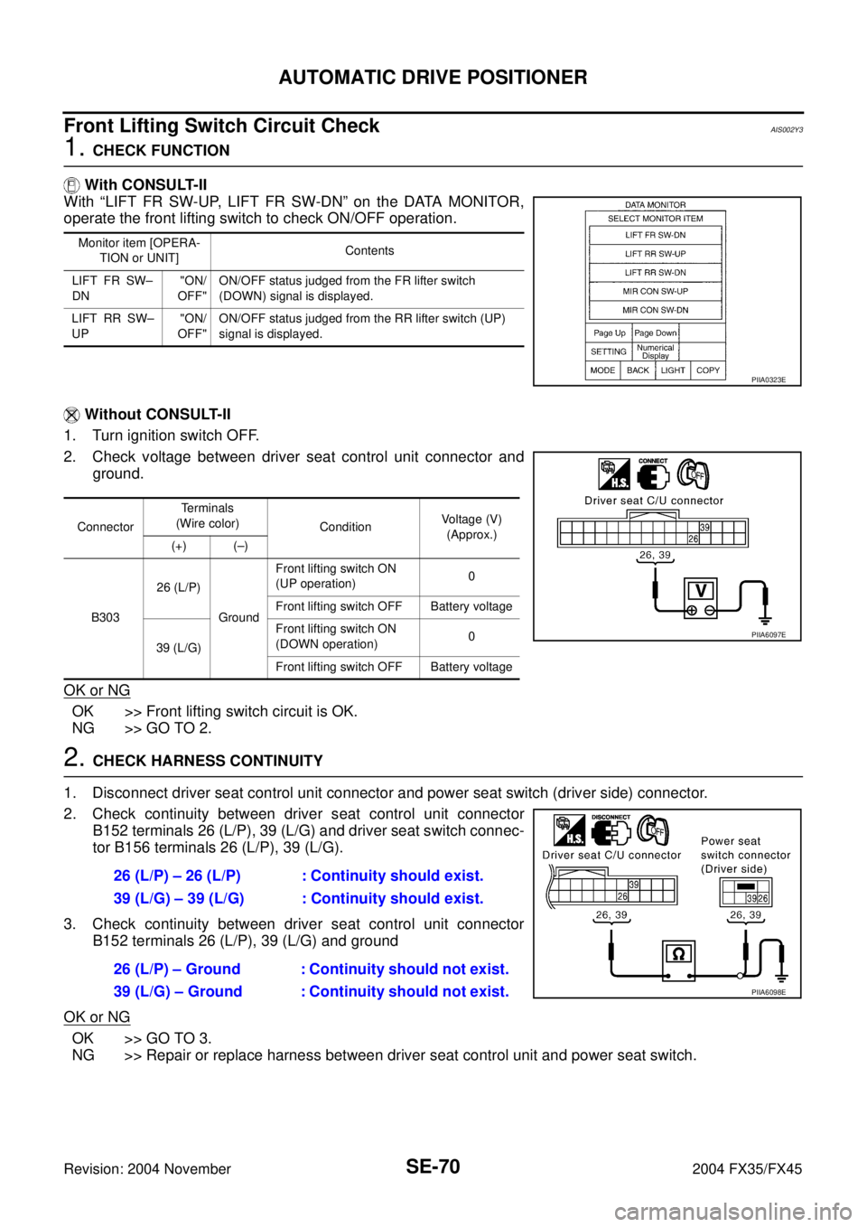
Front Lifting Switch Circuit CheckAIS002Y3
1. CHECK FUNCTION
With CONSULT-II
With “LIFT FR SW-UP, LIFT FR SW-DN” on the DATA MONITOR,
operate the front lifting switch to check ON/OFF operation.
Without CONSULT-II
1. Turn ignition switch OFF.
2. Check voltage between driver seat control unit connector and
ground.
OK or NG
OK >> Front lifting switch circuit is OK.
NG >> GO TO 2.
2. CHECK HARNESS CONTINUITY
1. Disconnect driver seat control unit connector and power seat switch (driver side) connector.
2. Check continuity between driver seat control unit connector
B152 terminals 26 (L/P), 39 (L/G) and driver seat switch connec-
tor B156 terminals 26 (L/P), 39 (L/G).
3. Check continuity between driver seat control unit connector
B152 terminals 26 (L/P), 39 (L/G) and ground
OK or NG
OK >> GO TO 3.
NG >> Repair or replace harness between driver seat control unit and power seat switch.
Monitor item [OPERA-
TION or UNIT]Contents
LIFT FR SW–
DN"ON/
OFF"ON/OFF status judged from the FR lifter switch
(DOWN) signal is displayed.
LIFT RR SW–
UP"ON/
OFF"ON/OFF status judged from the RR lifter switch (UP)
signal is displayed.
PIIA0323E
ConnectorTerminals
(Wire color)
ConditionVoltage (V)
(Approx.)
(+) (–)
B30326 (L/P)
GroundFront lifting switch ON
(UP operation)0
Front lifting switch OFF Battery voltage
39 (L/G)Front lifting switch ON
(DOWN operation)0
Front lifting switch OFF Battery voltage
PIIA6097E
26 (L/P) – 26 (L/P) : Continuity should exist.
39 (L/G) – 39 (L/G) : Continuity should exist.
26 (L/P) – Ground : Continuity should not exist.
39 (L/G) – Ground : Continuity should not exist.
PIIA6098E
Page 4200 of 4449
AUTOMATIC DRIVE POSITIONER
SE-71
C
D
E
F
G
H
J
K
L
MA
B
SE
Revision: 2004 November 2004 FX35/FX45
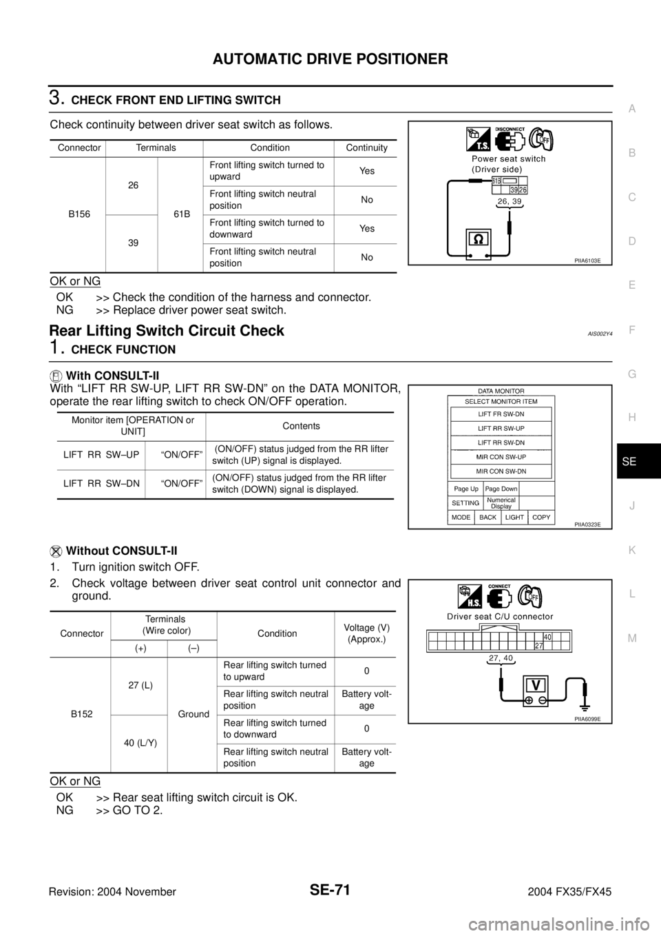
3. CHECK FRONT END LIFTING SWITCH
Check continuity between driver seat switch as follows.
OK or NG
OK >> Check the condition of the harness and connector.
NG >> Replace driver power seat switch.
Rear Lifting Switch Circuit CheckAIS002Y4
1. CHECK FUNCTION
With CONSULT-II
With “LIFT RR SW-UP, LIFT RR SW-DN” on the DATA MONITOR,
operate the rear lifting switch to check ON/OFF operation.
Without CONSULT-II
1. Turn ignition switch OFF.
2. Check voltage between driver seat control unit connector and
ground.
OK or NG
OK >> Rear seat lifting switch circuit is OK.
NG >> GO TO 2.
Connector Terminals Condition Continuity
B15626
61BFront lifting switch turned to
upwardYe s
Front lifting switch neutral
positionNo
39Front lifting switch turned to
downwardYe s
Front lifting switch neutral
positionNo
PIIA6103E
Monitor item [OPERATION or
UNIT]Contents
LIFT RR SW–UP “ON/OFF” (ON/OFF) status judged from the RR lifter
switch (UP) signal is displayed.
LIFT RR SW–DN “ON/OFF”(ON/OFF) status judged from the RR lifter
switch (DOWN) signal is displayed.
PIIA0323E
ConnectorTerminals
(Wire color)
ConditionVoltage (V)
(Approx.)
(+) (–)
B15227 (L)
GroundRear lifting switch turned
to upward0
Rear lifting switch neutral
positionBattery volt-
age
40 (L/Y)Rear lifting switch turned
to downward0
Rear lifting switch neutral
positionBattery volt-
age
PIIA6099E
Page 4201 of 4449

SE-72
AUTOMATIC DRIVE POSITIONER
Revision: 2004 November 2004 FX35/FX45
2. CHECK REAR LIFTING SWITCH HARNESS CONTINUITY
1. Disconnect driver seat control unit connector and driver power seat switch connector.
2. Check continuity between driver seat control unit connector
B152 terminals 27 (L), 40 (L/Y) and power seat switch (driver
side) connector B156 terminals 27 (L), 40 (L/Y).
3. Check continuity between driver seat control unit connector
B152 terminals 27 (L), 40 (L/Y) and ground.
OK or NG
OK >> GO TO 3.
NG >> Repair or replace harness between driver seat control unit and driver power seat switch (driver
side).
3. CHECK REAR LIFTING SWITCH
Check continuity between driver seat switch as follows.
OK or NG
OK >> Check the condition of the harness and connector.
NG >> Replace power seat switch (driver side).
Sliding Switch and Reclining Switch Ground Circuit CheckAIS003L1
1. CHECK POWER SEAT SWITCH
1. Disconnect power seat switch.
2. Check continuity between driver seat switch as follows.
OK or NG
OK >> GO TO 2.
NG >> Replace driver power seat switch.27 (L) – 27 (L) : Continuity should exist.
40 (L/Y) – 40 (L/Y) : Continuity should exist.
27 (L) – Ground : Continuity should not exist.
40 (L/Y) – Ground : Continuity should not exist.
PIIA6100E
Terminals Condition Continuity
27
61BRear lifting switch turned to upward Yes
Rear lifting switch neutral position No
40Rear lifting switch turned to downward Yes
Rear lifting switch neutral position No
PIIA6104E
Terminals Condition Continuity
24
61DSliding switch turned to forward Yes
Sliding switch neutral position No
37Sliding switch turned to backward Yes
Sliding switch neutral position No
PIIA6101E
Page 4202 of 4449
AUTOMATIC DRIVE POSITIONER
SE-73
C
D
E
F
G
H
J
K
L
MA
B
SE
Revision: 2004 November 2004 FX35/FX45
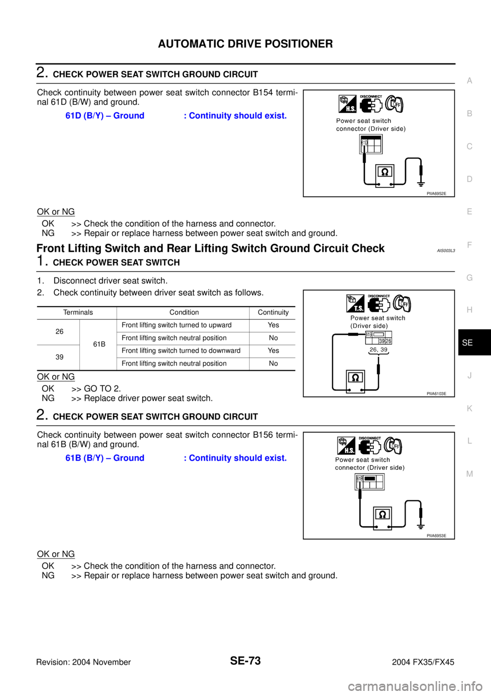
2. CHECK POWER SEAT SWITCH GROUND CIRCUIT
Check continuity between power seat switch connector B154 termi-
nal 61D (B/W) and ground.
OK or NG
OK >> Check the condition of the harness and connector.
NG >> Repair or replace harness between power seat switch and ground.
Front Lifting Switch and Rear Lifting Switch Ground Circuit CheckAIS003L3
1. CHECK POWER SEAT SWITCH
1. Disconnect driver seat switch.
2. Check continuity between driver seat switch as follows.
OK or NG
OK >> GO TO 2.
NG >> Replace driver power seat switch.
2. CHECK POWER SEAT SWITCH GROUND CIRCUIT
Check continuity between power seat switch connector B156 termi-
nal 61B (B/W) and ground.
OK or NG
OK >> Check the condition of the harness and connector.
NG >> Repair or replace harness between power seat switch and ground.61D (B/Y) – Ground : Continuity should exist.
PIIA6952E
Terminals Condition Continuity
26
61BFront lifting switch turned to upward Yes
Front lifting switch neutral position No
39Front lifting switch turned to downward Yes
Front lifting switch neutral position No
PIIA6103E
61B (B/Y) – Ground : Continuity should exist.
PIIA6953E