Page 4077 of 4449

RSU-18
SERVICE DATA
Revision: 2004 November 2004 FX35/FX45
SERVICE DATAPFP:00030
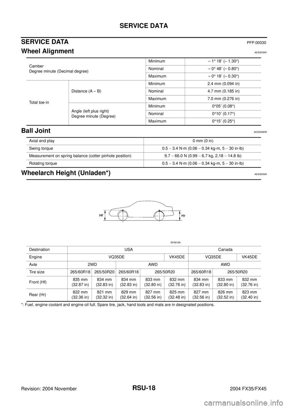
Wheel AlignmentAES000MV
Ball JointAES000MW
Wheelarch Height (Unladen*)AES000MX
*: Fuel, engine coolant and engine oil full. Spare tire, jack, hand tools and mats are in designated positions.Camber
Degree minute (Decimal degree)Minimum – 1° 18′ (– 1.30°)
Nominal – 0° 48′ (– 0.80°)
Maximum – 0° 18′ (– 0.30°)
Total toe-inDistance (A – B)Minimum 2.4 mm (0.094 in)
Nominal 4.7 mm (0.185 in)
Maximum 7.0 mm (0.276 in)
Angle (left plus right)
Degree minute (Degree)Minimum 0°05′ (0.08°)
Nominal 0°10′ (0.17°)
Maximum 0°15′ (0.25°)
Axial end play0 mm (0 in)
Swing torque 0.5 − 3.4 N·m (0.06 − 0.34 kg-m, 5 − 30 in-lb)
Measurement on spring balance (cotter pinhole position) 9.7 − 66.0 N (0.99 − 6.7 kg, 2.18 − 14.8 lb)
Rotating torque 0.5 − 3.4 N·m (0.06 − 0.34 kg-m, 5 − 30 in-lb)
Destination USA Canada
Engine VQ35DE VK45DE VQ35DE VK45DE
Axle 2WD AWD AWD
Tire size 265/60R18 265/50R20 265/60R18 265/50R20 265/60R18 265/50R20
Front (Hf)835 mm
(32.87 in)834 mm
(32.83 in)834 mm
(32.83 in)833 mm
(32.80 in)832 mm
(32.76 in)834 mm
(32.83 in)833 mm
(32.80 in)832 mm
(32.76 in)
Rear (Hr)822 mm
(32.36 in)821 mm
(32.32 in)829 mm
(32.64 in)827 mm
(32.56 in)825 mm
(32.48 in)827 mm
(32.56 in)826 mm
(32.52 in)823 mm
(32.40 in)
SFA818A
Page 4090 of 4449

SC-1
STARTING & CHARGING SYSTEM
K ELECTRICAL
CONTENTS
C
D
E
F
G
H
I
J
L
M
SECTION SC
A
B
SC
Revision: 2004 November 2004 FX35/FX45
STARTING & CHARGING SYSTEM
PRECAUTIONS .......................................................... 2
Precautions for Supplemental Restraint System
(SRS) “AIR BAG” and “SEAT BELT PRE-TEN-
SIONER” .................................................................. 2
Wiring Diagrams and Trouble Diagnosis .................. 2
PREPARATION ........................................................... 3
Special Service Tools ............................................... 3
Commercial Service Tools ........................................ 3
BATTERY .................................................................... 4
How to Handle Battery ............................................. 4
METHODS OF PREVENTING OVER-DIS-
CHARGE ............................................................... 4
CHECKING ELECTROLYTE LEVEL .................... 5
SPECIFIC GRAVITY CHECK ............................... 5
CHARGING THE BATTERY ................................. 6
Trouble Diagnosis with Battery/Starting/Charging
System Tester .......................................................... 6
DIAGNOSTIC RESULT ITEM CHART .................. 8
Removal and Installation .......................................... 9
REMOVAL ............................................................. 9
INSTALLATION ..................................................... 9
STARTING SYSTEM ................................................ 10
System Description ................................................ 10
Wiring Diagram — START — .................................. 11
VK45DE ENGINE MODELS ................................ 11
VQ35DE ENGINE MODELS ............................... 12
Trouble Diagnosis with Battery/Starting/Charging
System Tester ........................................................ 13
DIAGNOSTIC RESULT ITEM CHART ................ 13
WORK FLOW ...................................................... 14
DIAGNOSTIC PROCEDURE 1 ........................... 15
DIAGNOSTIC PROCEDURE 2 ........................... 16
MINIMUM SPECIFICATION OF CRANKING VOLTAGE REFERENCING COOLANT TEM-
PERATURE ......................................................... 16
Removal and Installation ........................................ 17
VK45DE ENGINE MODELS ................................ 17
VQ35DE ENGINE MODELS (2WD) .................... 18
VQ35DE ENGINE MODELS (AWD) .................... 19
Disassembly and Assembly .................................... 20
Inspection After Disassembly ................................. 22
PINION/CLUTCH CHECK ................................... 22
CHARGING SYSTEM ............................................... 23
System Description ................................................. 23
Wiring Diagram — CHARGE — ............................. 24
VK45DE ENGINE MODELS ................................ 24
VQ35DE ENGINE MODELS ............................... 25
Trouble Diagnosis with Battery/Starting/Charging
System Tester ......................................................... 26
DIAGNOSTIC RESULT ITEM CHART ................ 27
WORK FLOW ...................................................... 28
DIAGNOSTIC PROCEDURE 1 ........................... 29
DIAGNOSTIC PROCEDURE 2 ........................... 30
DIAGNOSTIC PROCEDURE 3 ........................... 31
DIAGNOSTIC PROCEDURE 4 ........................... 32
DIAGNOSTIC PROCEDURE 5 ........................... 33
MALFUNCTION INDICATOR .............................. 33
Removal and Installation ........................................ 34
VK45DE ENGINE MODELS ................................ 34
VQ35DE ENGINE MODELS ............................... 35
Disassembly and Assembly .................................... 37
SERVICE DATA AND SPECIFICATIONS (SDS) ...... 39
Battery .................................................................... 39
Starter ..................................................................... 39
Alternator ................................................................ 39
Page 4105 of 4449

SC-16
STARTING SYSTEM
Revision: 2004 November 2004 FX35/FX45
DIAGNOSTIC PROCEDURE 2
Check “S” Connector Circuit
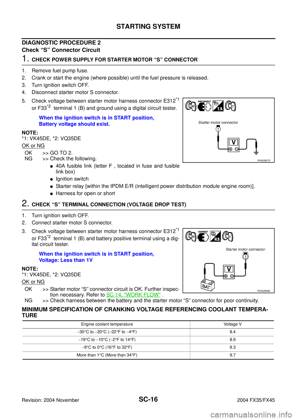
1. CHECK POWER SUPPLY FOR STARTER MOTOR “S” CONNECTOR
1. Remove fuel pump fuse.
2. Crank or start the engine (where possible) until the fuel pressure is released.
3. Turn ignition switch OFF.
4. Disconnect starter motor S connector.
5. Check voltage between starter motor harness connector E312
*1
or F33*2 terminal 1 (B) and ground using a digital circuit tester.
NOTE:
*1: VK45DE, *2: VQ35DE
OK or NG
OK >> GO TO 2.
NG >> Check the following.
�40A fusible link (letter F , located in fuse and fusible
link box)
�Ignition switch
�Starter relay [within the IPDM E/R (intelligent power distribution module engine room)].
�Harness for open or short
2. CHECK “S” TERMINAL CONNECTION (VOLTAGE DROP TEST)
1. Turn ignition switch OFF.
2. Connect starter motor S connector.
3. Check voltage between starter motor harness connector E312
*1
or F33*2 terminal 1 (B) and battery positive terminal using a dig-
ital circuit tester.
NOTE:
*1: VK45DE, *2: VQ35DE
OK or NG
OK >> Starter motor “S” connector circuit is OK. Further inspec-
tion necessary. Refer to SC-14, "
WORK FLOW" .
NG >> Check harness between the battery and the starter motor “S” connector for poor continuity.
MINIMUM SPECIFICATION OF CRANKING VOLTAGE REFERENCING COOLANT TEMPERA-
TURE
When the ignition switch is in START position,
Battery voltage should exist.
PKIA2807E
When the ignition switch is in START position,
Voltage: Less than 1V
PKIA2808E
Engine coolant temperature Voltage V
−30°C to −20°C (−22°F to −4°F) 8.4
−19°C to −10°C (−2°F to 14°F) 8.9
−9°C to 0°C (16°F to 32°F) 9.3
More than 1°C (More than 34°F) 9.7