Page 3642 of 4449

FRONT FOG LAMP
LT-87
C
D
E
F
G
H
I
J
L
MA
B
LT
Revision: 2004 November 2004 FX35/FX45
Aiming AdjustmentAKS007CT
The fog lamp is a semi-sealed beam type which uses a replaceable halogen bulb. Before performing aiming
adjustment, make sure of the following.
�Keep all tires inflated to correct pressure.
�Place vehicle on level ground.
�See that vehicle is unloaded (except for full levels of coolant, engine oil and fuel, and spare tire, jack, and
tools). Have the driver or equivalent weight placed in driver seat.
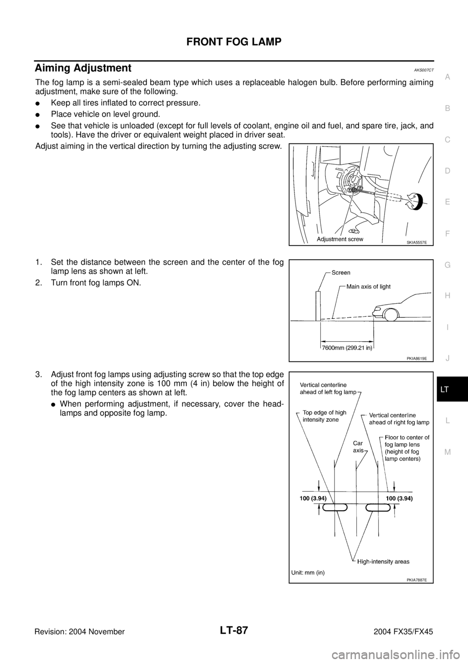
Adjust aiming in the vertical direction by turning the adjusting screw.
1. Set the distance between the screen and the center of the fog
lamp lens as shown at left.
2. Turn front fog lamps ON.
3. Adjust front fog lamps using adjusting screw so that the top edge
of the high intensity zone is 100 mm (4 in) below the height of
the fog lamp centers as shown at left.
�When performing adjustment, if necessary, cover the head-
lamps and opposite fog lamp.
SKIA5557E
PKIA8619E
PKIA7887E
Page 4028 of 4449

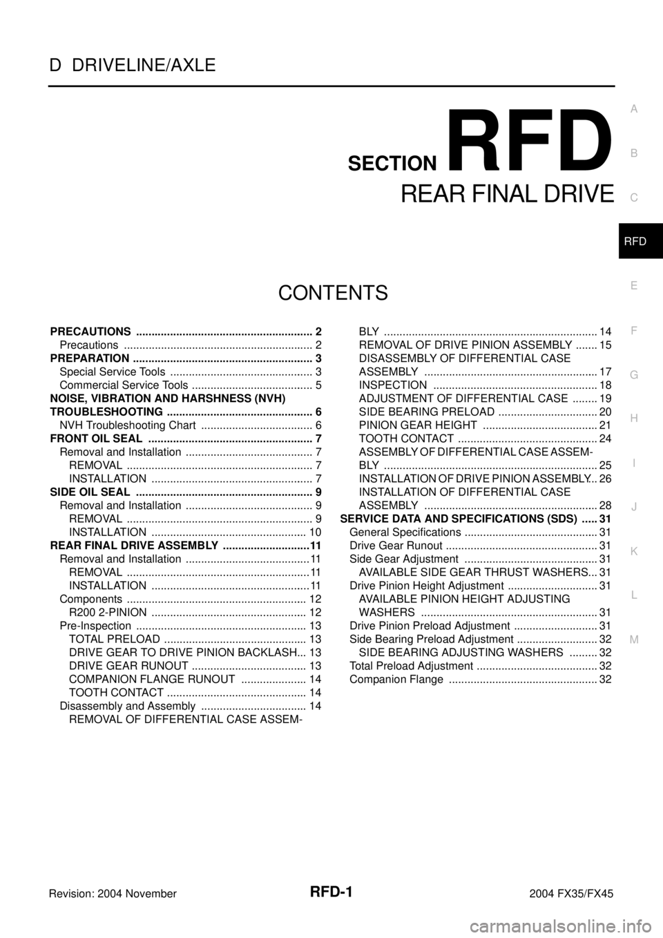
RFD-1
REAR FINAL DRIVE
D DRIVELINE/AXLE
CONTENTS
C
E
F
G
H
I
J
K
L
M
SECTION RFD
A
B
RFD
Revision: 2004 November 2004 FX35/FX45
REAR FINAL DRIVE
PRECAUTIONS .......................................................... 2
Precautions .............................................................. 2
PREPARATION ........................................................... 3
Special Service Tools ............................................... 3
Commercial Service Tools ........................................ 5
NOISE, VIBRATION AND HARSHNESS (NVH)
TROUBLESHOOTING ................................................ 6
NVH Troubleshooting Chart ..................................... 6
FRONT OIL SEAL ...................................................... 7
Removal and Installation .......................................... 7
REMOVAL ............................................................. 7
INSTALLATION ..................................................... 7
SIDE OIL SEAL .......................................................... 9
Removal and Installation .......................................... 9
REMOVAL ............................................................. 9
INSTALLATION ................................................... 10
REAR FINAL DRIVE ASSEMBLY .............................11
Removal and Installation ......................................... 11
REMOVAL ............................................................ 11
INSTALLATION .................................................... 11
Components ........................................................... 12
R200 2-PINION ................................................... 12
Pre-Inspection ........................................................ 13
TOTAL PRELOAD ............................................... 13
DRIVE GEAR TO DRIVE PINION BACKLASH ... 13
DRIVE GEAR RUNOUT ...................................... 13
COMPANION FLANGE RUNOUT ...................... 14
TOOTH CONTACT .............................................. 14
Disassembly and Assembly ................................... 14
REMOVAL OF DIFFERENTIAL CASE ASSEM-BLY ...................................................................... 14
REMOVAL OF DRIVE PINION ASSEMBLY ........ 15
DISASSEMBLY OF DIFFERENTIAL CASE
ASSEMBLY ......................................................... 17
INSPECTION ...................................................... 18
ADJUSTMENT OF DIFFERENTIAL CASE ......... 19
SIDE BEARING PRELOAD ................................. 20
PINION GEAR HEIGHT ...................................... 21
TOOTH CONTACT .............................................. 24
ASSEMBLY OF DIFFERENTIAL CASE ASSEM-
BLY ...................................................................... 25
INSTALLATION OF DRIVE PINION ASSEMBLY ... 26
INSTALLATION OF DIFFERENTIAL CASE
ASSEMBLY ......................................................... 28
SERVICE DATA AND SPECIFICATIONS (SDS) ...... 31
General Specifications ............................................ 31
Drive Gear Runout .................................................. 31
Side Gear Adjustment ............................................ 31
AVAILABLE SIDE GEAR THRUST WASHERS ... 31
Drive Pinion Height Adjustment .............................. 31
AVAILABLE PINION HEIGHT ADJUSTING
WASHERS .......................................................... 31
Drive Pinion Preload Adjustment ............................ 31
Side Bearing Preload Adjustment ........................... 32
SIDE BEARING ADJUSTING WASHERS .......... 32
Total Preload Adjustment ........................................ 32
Companion Flange ................................................. 32
Page 4058 of 4449

SERVICE DATA AND SPECIFICATIONS (SDS)
RFD-31
C
E
F
G
H
I
J
K
L
MA
B
RFD
Revision: 2004 November 2004 FX35/FX45
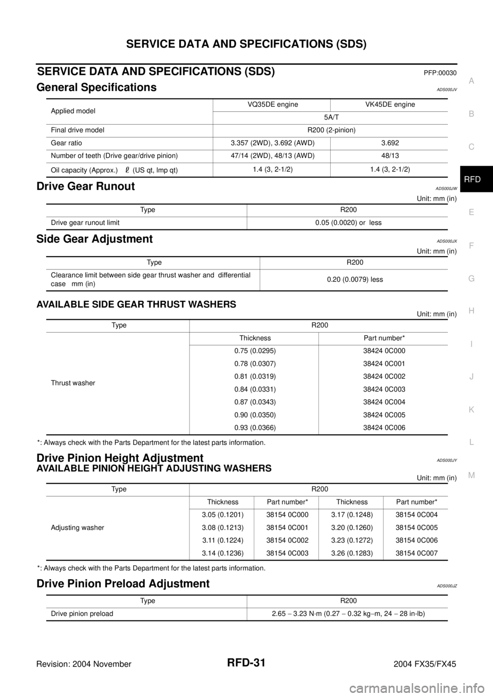
SERVICE DATA AND SPECIFICATIONS (SDS)PFP:00030
General SpecificationsADS000JV
Drive Gear RunoutADS000JW
Unit: mm (in)
Side Gear Adjustment ADS000JX
Unit: mm (in)
AVAILABLE SIDE GEAR THRUST WASHERS
Unit: mm (in)
*: Always check with the Parts Department for the latest parts information.
Drive Pinion Height AdjustmentADS000JY
AVAILABLE PINION HEIGHT ADJUSTING WASHERS
Unit: mm (in)
*: Always check with the Parts Department for the latest parts information.
Drive Pinion Preload AdjustmentADS000JZ
Applied modelVQ35DE engine VK45DE engine
5A/T
Final drive model R200 (2-pinion)
Gear ratio 3.357 (2WD), 3.692 (AWD) 3.692
Number of teeth (Drive gear/drive pinion) 47/14 (2WD), 48/13 (AWD) 48/13
Oil capacity (Approx.) (US qt, lmp qt)1.4 (3, 2-1/2) 1.4 (3, 2-1/2)
Type R200
Drive gear runout limit 0.05 (0.0020) or less
Type R200
Clearance limit between side gear thrust washer and differential
case mm (in)0.20 (0.0079) less
Type R20 0
Thrust washerThickness Part number*
0.75 (0.0295) 38424 0C000
0.78 (0.0307) 38424 0C001
0.81 (0.0319) 38424 0C002
0.84 (0.0331) 38424 0C003
0.87 (0.0343) 38424 0C004
0.90 (0.0350) 38424 0C005
0.93 (0.0366) 38424 0C006
Type R200
Adjusting washerThickness Part number* Thickness Part number*
3.05 (0.1201) 38154 0C000 3.17 (0.1248) 38154 0C004
3.08 (0.1213) 38154 0C001 3.20 (0.1260) 38154 0C005
3.11 (0.1224) 38154 0C002 3.23 (0.1272) 38154 0C006
3.14 (0.1236) 38154 0C003 3.26 (0.1283) 38154 0C007
Type R200
Drive pinion preload 2.65 − 3.23 N·m (0.27 − 0.32 kg−m, 24 − 28 in-lb)
Page 4440 of 4449

REAR WIPER AND WASHER SYSTEM
WW-49
C
D
E
F
G
H
I
J
L
MA
B
WW
Revision: 2004 November 2004 FX35/FX45
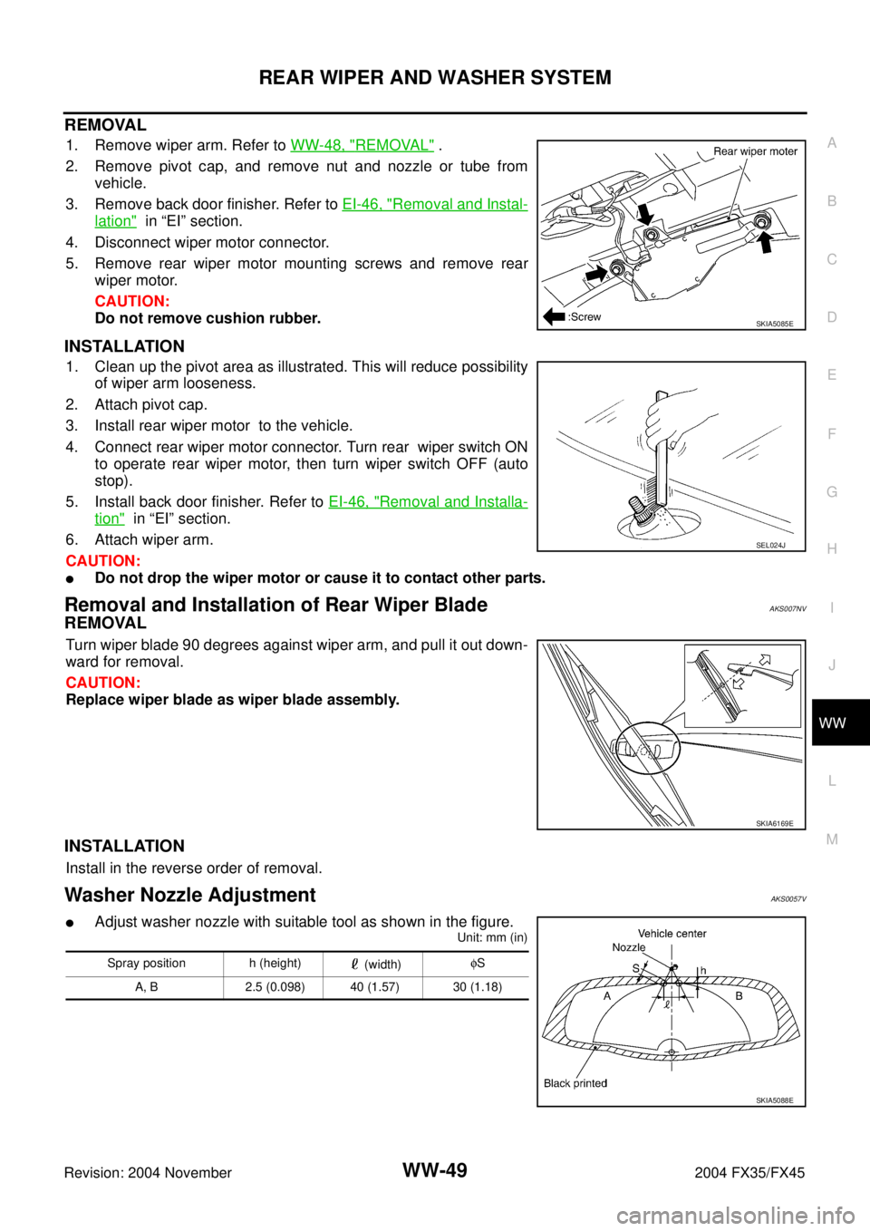
REMOVAL
1. Remove wiper arm. Refer to WW-48, "REMOVAL" .
2. Remove pivot cap, and remove nut and nozzle or tube from
vehicle.
3. Remove back door finisher. Refer to EI-46, "
Removal and Instal-
lation" in “EI” section.
4. Disconnect wiper motor connector.
5. Remove rear wiper motor mounting screws and remove rear
wiper motor.
CAUTION:
Do not remove cushion rubber.
INSTALLATION
1. Clean up the pivot area as illustrated. This will reduce possibility
of wiper arm looseness.
2. Attach pivot cap.
3. Install rear wiper motor to the vehicle.
4. Connect rear wiper motor connector. Turn rear wiper switch ON
to operate rear wiper motor, then turn wiper switch OFF (auto
stop).
5. Install back door finisher. Refer to EI-46, "
Removal and Installa-
tion" in “EI” section.
6. Attach wiper arm.
CAUTION:
�Do not drop the wiper motor or cause it to contact other parts.
Removal and Installation of Rear Wiper BladeAKS007NV
REMOVAL
Turn wiper blade 90 degrees against wiper arm, and pull it out down-
ward for removal.
CAUTION:
Replace wiper blade as wiper blade assembly.
INSTALLATION
Install in the reverse order of removal.
Washer Nozzle AdjustmentAKS0057V
�Adjust washer nozzle with suitable tool as shown in the figure.
Unit: mm (in)
SKIA5085E
SEL024J
SKIA6169E
Spray position h (height)
(width)φS
A, B 2.5 (0.098) 40 (1.57) 30 (1.18)
SKIA5088E
Page:
< prev 1-8 9-16 17-24