Page 3814 of 4449
ENGINE MAINTENANCE (VK45DE ENGINE)
MA-27
C
D
E
F
G
H
I
J
K
MA
B
MA
Revision: 2004 November 2004 FX35/FX45
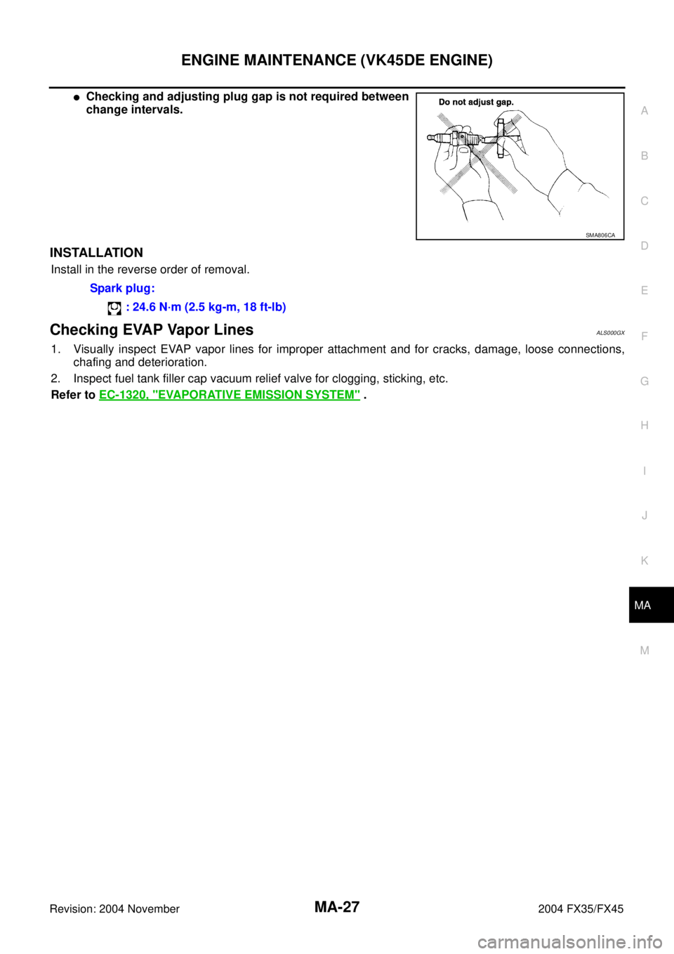
�Checking and adjusting plug gap is not required between
change intervals.
INSTALLATION
Install in the reverse order of removal.
Checking EVAP Vapor LinesALS000GX
1. Visually inspect EVAP vapor lines for improper attachment and for cracks, damage, loose connections,
chafing and deterioration.
2. Inspect fuel tank filler cap vacuum relief valve for clogging, sticking, etc.
Refer to EC-1320, "
EVAPORATIVE EMISSION SYSTEM" .
SMA806CA
Spark plug:
: 24.6 N·m (2.5 kg-m, 18 ft-lb)
Page 3815 of 4449

MA-28
CHASSIS AND BODY MAINTENANCE
Revision: 2004 November 2004 FX35/FX45
CHASSIS AND BODY MAINTENANCEPFP:00100
Checking Exhaust SystemALS000FG
Check exhaust pipes, muffler and mounting for improper attachment,
leaks, cracks, damage, chafing or deterioration.
Checking A/T FluidALS000GB
1. Warm up engine.
2. Check for fluid leakage.
3. Remove the tightening bolt for ATF level gauge.
4. Before driving, fluid level can be checked at fluid temperatures of 30 to 50°C (86 to 122°F) using “COLD”
range on ATF level gauge as follows.
a. Park vehicle on level surface and set parking brake.
b. Start engine and move selector lever through each gear position. Leave selector lever in “P” position.
c. Check fluid level with engine idling.
d. Remove ATF level gauge and wipe clean with lint-free paper.
CAUTION:
When wiping away the fluid level gauge, always use lint-free paper, not a cloth one.
e. Re-insert ATF level gauge into charging pipe as far as it will go.
CAUTION:
To check fluid level, insert the ATF level gauge until the cap contacts the end of the charging pipe,
with the gauge reversed from the normal attachment conditions.
f. Remove ATF level gauge and note reading. If reading is at low side of range, add fluid to the charging
pipe.
CAUTION:
Do not overfill.
5. Drive vehicle for approximately 5 minutes in urban areas.
6. Make the fluid temperature approximately 65°C (149°F).
SMA211A
Page 3823 of 4449

MA-36
CHASSIS AND BODY MAINTENANCE
Revision: 2004 November 2004 FX35/FX45
Checking Power Steering Fluid and LinesALS000FV
Check fluid level in reservoir tank with engine off.
Use “HOT” range at fluid temperatures of 50 to 80°C (122 to 176°F)
or “COLD” range at fluid temperatures of 0 to 30°C (32 to 86°F).
CAUTION:
�Do not overfill.
�Recommended fluid is Genuine NISSAN PSF or equivalent.
Refer to MA-12, "
RECOMMENDED FLUIDS AND LUBRI-
CANTS"
�Check lines for improper attachment, leaks, cracks, dam-
age, loose connections, chafing and deterioration.
�Check rack boots for accumulation of power steering fluid.
Axle and Suspension PartsALS000FW
Check front and rear axle and suspension parts for excessive play,
cracks, wear or other damage.
�Shake each wheel to check for excessive play.
�Check wheel bearings for smooth operation.
�Check axle and suspension nuts and bolts for looseness.
�Check strut (shock absorber) for oil leakage or other damage.
�Check suspension ball joint for grease leakage and ball joint
dust cover for cracks or other damage.
SST850C
SST851C
SMA525A
SFA392B
Page 3824 of 4449
CHASSIS AND BODY MAINTENANCE
MA-37
C
D
E
F
G
H
I
J
K
MA
B
MA
Revision: 2004 November 2004 FX35/FX45
Drive ShaftALS000FX
Check boot and drive shaft for cracks, wear, damage and grease
leakage.
Lubricating Locks, Hinges and Hood LatchALS000FY
SFA108A
PIIA7009E
Page 3829 of 4449

PB-2
PARKING BRAKE SYSTEM
Revision: 2004 November 2004 FX35/FX45
PARKING BRAKE SYSTEMPFP:36010
On-Vehicle ServiceAFS001TJ
PEDAL STROKE
�When parking brake pedal is operated with a force of 200 N (20.4 kg, 44.9 lb), make sure the stroke is
within the specified number of notches. (Check it by listening and counting the ratchet clicks.)
INSPECT COMPONENTS
�Make sure the components are attached properly (check for looseness, backlash, etc.).
�Check parking brake pedal assembly for bend, damage and cracks, and replace if necessary.
�Check cable for wear and damage, and replace if necessary.
�Check parking brake warning lamp switch for malfunction, and replace if necessary.
ADJUSTMENT
�To perform adjustment operations, remove tire from the vehicle with power tool.
1. Insert a deep socket wrench to rotate adjusting nut and loosen
cable sufficiently. Then, return pedal.
2. Using wheel nuts, fix disc to hub and prevent it from tilting.
3. Remove adjusting hole plug installed on disc. Using a flat-
bladed screwdriver, turn Adjuster in direction A as shown in the
figure until disc rotor is locked. After locking, turn adjuster in the
opposite direction by 5 or 6 notches.
4. Rotate disc rotor to make sure there is no drag. Install adjusting
hole plug.
5. Adjust cable as follows:
a. Operate pedal 10 or more times with a force of 490 N (50 kg,
11 0 l b ) .
b. Rotate adjusting nut with deep socket to adjust pedal stroke.
CAUTION:
Do not reuse adjusting nut after removing it.
c. When parking brake pedal is operated with a force of 200 N (20.4 kg, 44.9 lb), make sure the stroke is
within the specified number of notches. (Check it by listening and counting the ratchet clicks.)
d. With pedal completely returned, make sure there is no drag on rear brake.Pedal stroke : 4 − 5 notches
SFIA1139E
Pedal stroke : 4 − 5 notches
PFIA0295E
Page 3833 of 4449

PB-6
PARKING BRAKE SHOE
Revision: 2004 November 2004 FX35/FX45
INSPECTION AFTER REMOVAL
Lining Thickness Inspection
�Check thickness of lining.
Drum Inner Diameter Inspection
�Check drum inner diameter.
Other Inspections
�Check shoe sliding surface for excessive wear and damage.
�Check anti-rattle pin for excessive wear and corrosion.
�Check return spring for sagging.
�Check adjustor for rough operation.
�Check either visually or with a vernier caliper to see if there is
any excessive wear, cracks, or damage inside drum.
INSTALLATION
Be careful of the following:
�Refer to “Component Parts Location” and apply brake grease to the specified points during assembly.
�Assemble adjuster so that threaded part expands when rotating
it in the direction shown by the arrow.
�Shorten adjuster by rotating it.
�When disassembling adjuster, apply PBC (Poly Butyl Cuprysil)
grease or silicone based grease to the threads.
�After replacing brake shoes or disc rotors, or if brakes do not
function well, perform break-in operation as follows.
1. Adjust parking brake pedal stroke to the specified stroke.
2. Perform parking brake break-in (drag run) operation by driving
the vehicle under the following conditions:
3. After break-in operation, check lever stroke of parking brake. Readjust if it is no longer at the specified
stroke.
�To prevent lining from getting too hot, allow a cool off period of approximately 5 minutes after every
break-in operation.
�Do not perform excessive break-in operations, because it may cause uneven or early wear of lining.Standard thickness (A) : 3.2 mm (0.126 in)
Repair limit thickness (A) : 1.5 mm (0.059 in)
SBR021A
Standard inner diameter : 190 mm (7.48 in)
Maximum inner diameter : 191 mm (7.52 in)
SBR768A
Drive forward
�Perform the following
�Vehicle speed approx. 40 km/h (25 MPH) set (forward)
�Parking brake operating force approx. 100 N (10 kg, 45lb) set
�Distance approx. 100m (328ft)
SFIA0153E
Page 3910 of 4449
HARNESS CONNECTOR
PG-75
C
D
E
F
G
H
I
J
L
MA
B
PG
Revision: 2004 November 2004 FX35/FX45
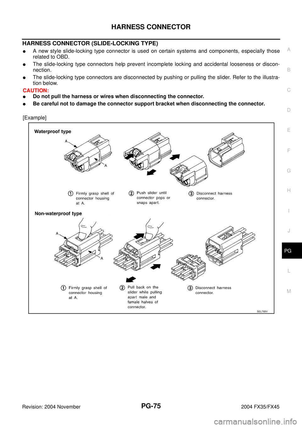
HARNESS CONNECTOR (SLIDE-LOCKING TYPE)
�A new style slide-locking type connector is used on certain systems and components, especially those
related to OBD.
�The slide-locking type connectors help prevent incomplete locking and accidental looseness or discon-
nection.
�The slide-locking type connectors are disconnected by pushing or pulling the slider. Refer to the illustra-
tion below.
CAUTION:
�Do not pull the harness or wires when disconnecting the connector.
�Be careful not to damage the connector support bracket when disconnecting the connector.
[Example]
SEL769V
Page 3923 of 4449

PR-4
FRONT PROPELLER SHAFT
Revision: 2004 November 2004 FX35/FX45
FRONT PROPELLER SHAFTPFP:37200
On-Vehicle ServiceADS000KL
PROPELLER SHAFT VIBRATION
If vibration is present at high speed, inspect propeller shaft runout first.
1. Measure propeller shaft runout at several points by rotating final
drive companion flange with your hands.
2. If runout still exceeds specifications, disconnect propeller shaft
at the final drive companion flange; then rotate companion
flange 90, 180, 270 degrees and reconnect propeller shaft.
3. Check runout again. If runout still exceeds specifications,
replace propeller shaft assembly.
4. Check the vibration by driving the vehicle.
APPEARANCE CHECKING
�Inspect propeller shaft tube surface for dents or cracks. If damaged, replace propeller shaft assembly.
Removal and InstallationADS000KM
REMOVAL
1. Remove the front and rear engine undercover with power tool.
2. Remove the front cross bar with power tool. Refer to FSU-6, "
FRONT SUSPENSION ASSEMBLY" .
3. Remove the exhaust front tube bracket with power tool. Refer to EX-3, "
EXHAUST SYSTEM" .
4. Disconnect the heated oxygen sensor harness connector.
5. Remove the exhaust front tube mounting nuts with power tool. Refer to EX-3, "
EXHAUST SYSTEM" .
6. Remove the right bank catalytic converter with power tool. Refer to EM-26, "
Removal and Installation"
(VQ35DE) or EM-178, "Removal and Installation" (VK45DE).
7. Remove the power steering piping mounting bolts. Refer to PS-
41, "HYDRAULIC LINE" .
8. Remove the power steering gear box fixing bolts to secure work-
ing area for removal of propeller shaft. Refer to PS-19, "
POWER
STEERING GEAR AND LINKAGE" .
CAUTION:
Be careful not to damage the steering gear box piping dur-
ing removal.Propeller shaft runout limit : 0.6 mm (0.024 in) or less
SDIA1759E
SDIA1515E
1. Propeller shaft assembly 2. O-ring
SDIA1516E