Page 347 of 4449

AT-270
TRANSMISSION ASSEMBLY
Revision: 2004 November 2004 FX35/FX45
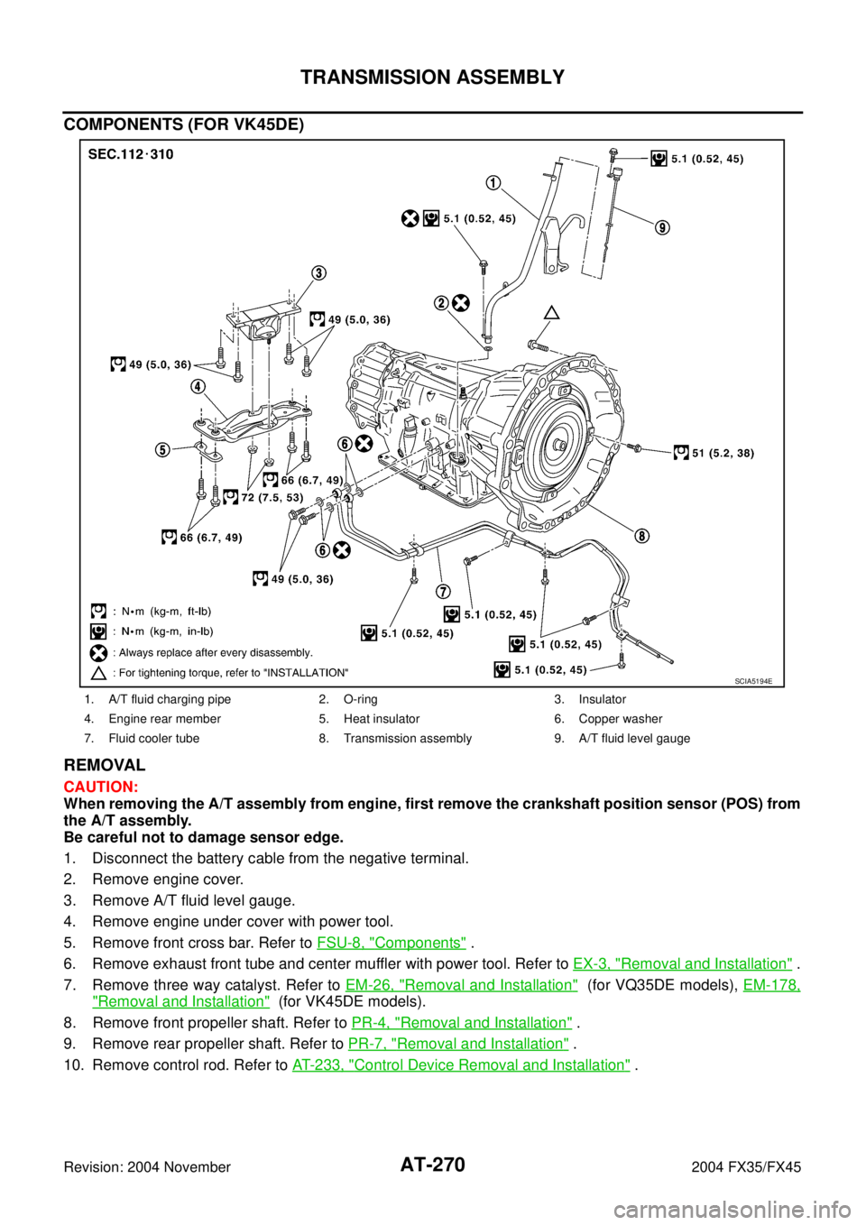
COMPONENTS (FOR VK45DE)
REMOVAL
CAUTION:
When removing the A/T assembly from engine, first remove the crankshaft position sensor (POS) from
the A/T assembly.
Be careful not to damage sensor edge.
1. Disconnect the battery cable from the negative terminal.
2. Remove engine cover.
3. Remove A/T fluid level gauge.
4. Remove engine under cover with power tool.
5. Remove front cross bar. Refer to FSU-8, "
Components" .
6. Remove exhaust front tube and center muffler with power tool. Refer to EX-3, "
Removal and Installation" .
7. Remove three way catalyst. Refer to EM-26, "
Removal and Installation" (for VQ35DE models), EM-178,
"Removal and Installation" (for VK45DE models).
8. Remove front propeller shaft. Refer to PR-4, "
Removal and Installation" .
9. Remove rear propeller shaft. Refer to PR-7, "
Removal and Installation" .
10. Remove control rod. Refer to AT- 2 3 3 , "
Control Device Removal and Installation" .
1. A/T fluid charging pipe 2. O-ring 3. Insulator
4. Engine rear member 5. Heat insulator 6. Copper washer
7. Fluid cooler tube 8. Transmission assembly 9. A/T fluid level gauge
SCIA5194E
Page 348 of 4449

TRANSMISSION ASSEMBLY
AT-271
D
E
F
G
H
I
J
K
L
MA
B
AT
Revision: 2004 November 2004 FX35/FX45
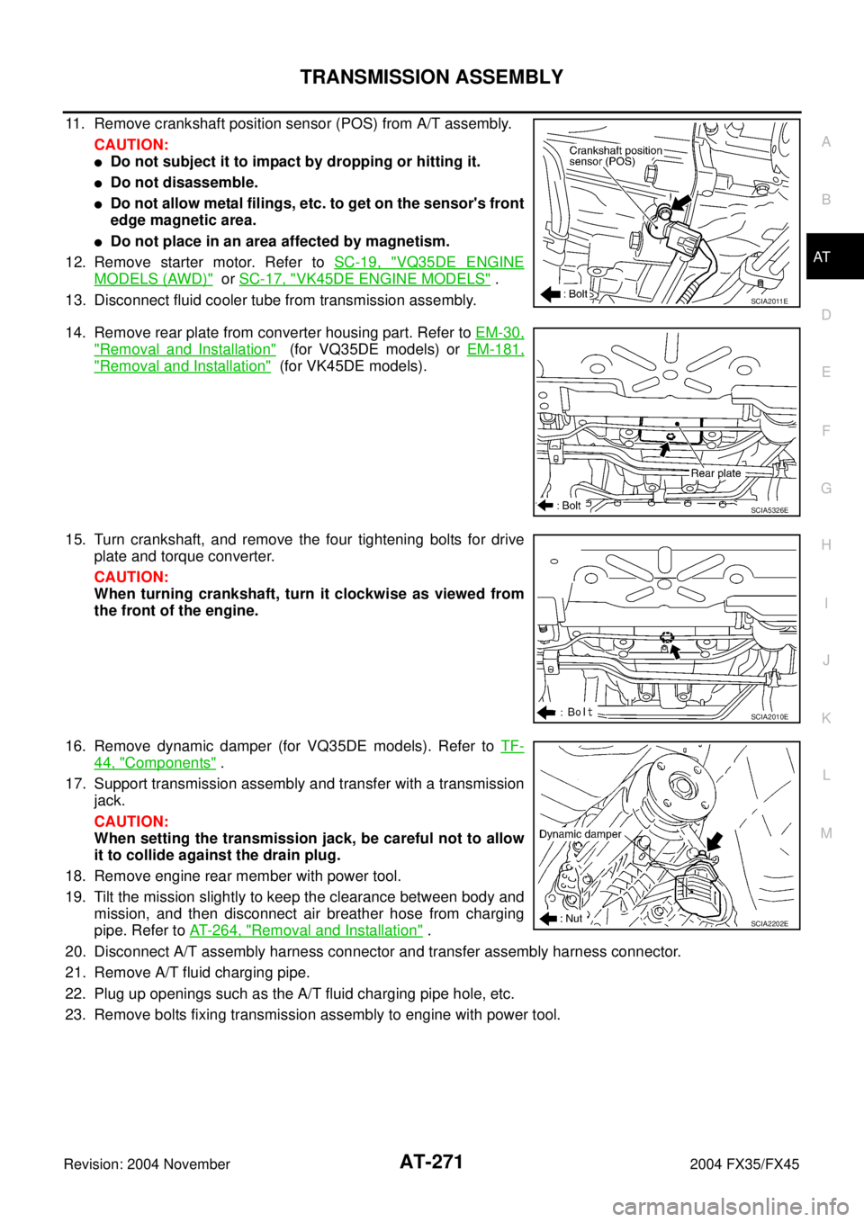
11. Remove crankshaft position sensor (POS) from A/T assembly.
CAUTION:
�Do not subject it to impact by dropping or hitting it.
�Do not disassemble.
�Do not allow metal filings, etc. to get on the sensor's front
edge magnetic area.
�Do not place in an area affected by magnetism.
12. Remove starter motor. Refer to SC-19, "
VQ35DE ENGINE
MODELS (AWD)" or SC-17, "VK45DE ENGINE MODELS" .
13. Disconnect fluid cooler tube from transmission assembly.
14. Remove rear plate from converter housing part. Refer to EM-30,
"Removal and Installation" (for VQ35DE models) or EM-181,
"Removal and Installation" (for VK45DE models).
15. Turn crankshaft, and remove the four tightening bolts for drive
plate and torque converter.
CAUTION:
When turning crankshaft, turn it clockwise as viewed from
the front of the engine.
16. Remove dynamic damper (for VQ35DE models). Refer to TF-
44, "Components" .
17. Support transmission assembly and transfer with a transmission
jack.
CAUTION:
When setting the transmission jack, be careful not to allow
it to collide against the drain plug.
18. Remove engine rear member with power tool.
19. Tilt the mission slightly to keep the clearance between body and
mission, and then disconnect air breather hose from charging
pipe. Refer to AT- 2 6 4 , "
Removal and Installation" .
20. Disconnect A/T assembly harness connector and transfer assembly harness connector.
21. Remove A/T fluid charging pipe.
22. Plug up openings such as the A/T fluid charging pipe hole, etc.
23. Remove bolts fixing transmission assembly to engine with power tool.
SCIA2011E
SCIA5326E
SCIA2010E
SCIA2202E
Page 350 of 4449

TRANSMISSION ASSEMBLY
AT-273
D
E
F
G
H
I
J
K
L
MA
B
AT
Revision: 2004 November 2004 FX35/FX45
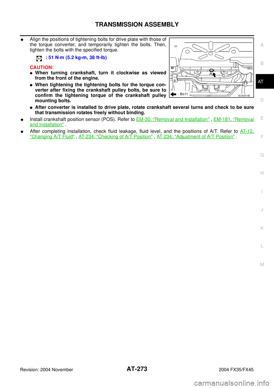
�Align the positions of tightening bolts for drive plate with those of
the torque converter, and temporarily tighten the bolts. Then,
tighten the bolts with the specified torque.
CAUTION:
�When turning crankshaft, turn it clockwise as viewed
from the front of the engine.
�When tightening the tightening bolts for the torque con-
verter after fixing the crankshaft pulley bolts, be sure to
confirm the tightening torque of the crankshaft pulley
mounting bolts.
�After converter is installed to drive plate, rotate crankshaft several turns and check to be sure
that transmission rotates freely without binding.
�Install crankshaft position sensor (POS). Refer to EM-30, "Removal and Installation" , EM-181, "Removal
and Installation" .
�After completing installation, check fluid leakage, fluid level, and the positions of A/T. Refer to AT- 1 2 ,
"Changing A/T Fluid" , AT- 2 3 4 , "Checking of A/T Position" , AT- 2 3 4 , "Adjustment of A/T Position" . : 51 N·m (5.2 kg-m, 38 ft-lb)
SCIA2010E
Page 356 of 4449
OVERHAUL
AT-279
D
E
F
G
H
I
J
K
L
MA
B
AT
Revision: 2004 November 2004 FX35/FX45
7. Pawl shaft 8. Seal ring 9. Needle bearing
10. Revolution sensor 11. Parking gear 12. Output shaft
13. Bearing race 14. Needle bearing 15. Manual plate
16. Parking rod 17. Manual shaft oil seal 18. Manual shaft
19. O-ring 20. Band servo anchor end pin 21. Detent spring
22. Spacer 23. Seal ring 24. Snap ring
25. O-ring 26. Transmission case 27. Retaining pin
28. Return spring 29. O-ring 30. Servo assembly
31. Snap ring 32. Control valve with TCM 33. Bracket
34. A/T fluid temperature sensor 2 35. Oil pan gasket 36. Oil pan
37. Magnet 38. Drain plug 39. Drain plug gasket
40. Oil pan mounting bolt
Page 358 of 4449
OVERHAUL
AT-281
D
E
F
G
H
I
J
K
L
MA
B
AT
Revision: 2004 November 2004 FX35/FX45
7. Pawl shaft 8. Self-sealing bolt 9. Seal ring
10. Needle bearing 11. Gasket 12. Revolution sensor
13. Parking gear 14. Output shaft 15. Bearing race
16. Needle bearing 17. Manual plate 18. Parking rod
19. Manual shaft oil seal 20. Manual shaft 21. O-ring
22. Band servo anchor end pin 23. Detent spring 24. Spacer
25. Seal ring 26. Return spring 27. O-ring
28. Servo assembly 29. Snap ring 30. Control valve with TCM
31. Bracket 32. A/T fluid temperature sensor 2 33. Oil pan
34. Magnet 35. Drain plug 36. Drain plug gasket
37. Oil pan mounting bolt 38. Oil pan gasket 39. O-ring
40. Snap ring 41. Transmission case 42. Retaining pin
Page 369 of 4449
AT-292
DISASSEMBLY
Revision: 2004 November 2004 FX35/FX45
28. Remove oil pan and oil pan gasket.
29. Check foreign materials in oil pan to help determine causes of
malfunction. If the A/T fluid is very dark, smells burned, or con-
tains foreign particles, the frictional material (clutches, band)
may need replacement. A tacky film that will not wipe clean indi-
cates varnish build up. Varnish can cause valves, servo, and
clutches to stick and can inhibit pump pressure.
�If frictional material is detected, perform A/T fluid cooler
cleaning. Refer to AT- 1 4 , "
A/T Fluid Cooler Cleaning" .
30. Remove magnets from oil pan.
31. Disconnect A/T fluid temperature sensor 2 connector.
CAUTION:
Be careful not to damage connector.
32. Straighten terminal clip to free A/T fluid temperature sensor 2
harness.
SCIA2308E
SCIA5199E
SCIA5200E
SCIA5023E
SCIA5146E
Page 370 of 4449
DISASSEMBLY
AT-293
D
E
F
G
H
I
J
K
L
MA
B
AT
Revision: 2004 November 2004 FX35/FX45
33. Disconnect revolution sensor connector.
CAUTION:
Be careful not to damage connector.
34. Straighten terminal clips to free revolution sensor harness.
35. Remove bolts A, B and C from control valve with TCM.
36. Remove control valve with TCM from transmission case.
CAUTION:
When removing, be careful with the manual valve notch and
manual plate height.Remove it vertically.
37. Remove A/T fluid temperature sensor 2 with bracket from con-
trol valve with TCM.
SCIA5024E
SCIA5293E
Bolt symbol Length mm (in) Number of bolts
A 42 (1.65) 5
B 55 (2.17) 6
C 40 (1.57) 1
SCIA5025E
SCIA5260E
SCIA5301E
Page 371 of 4449
AT-294
DISASSEMBLY
Revision: 2004 November 2004 FX35/FX45
38. Remove bracket from A/T fluid temperature sensor 2.
39. Remove O-ring from A/T assembly harness connector.
40. Remove rear extension assembly (2WD models) or adapter case assembly (AWD models) according to
the following procedures.
a.2WD models
i. Remove tightening bolts for rear extension assembly and trans-
mission case.
ii. Tap rear extension assembly with soft hammer.
SCIA5264E
SCIA5155E
SCIA3426E
SCIA5028E