PRECAUTIONS
PS-3
C
D
E
F
H
I
J
K
L
MA
B
PS
Revision: 2004 November 2004 FX35/FX45
PRECAUTIONSPFP:00001
Precautions for Supplemental Restraint System (SRS) “AIR BAG” and “SEAT
BELT PRE-TENSIONER”
AGS000GO
The Supplemental Restraint System such as “AIR BAG” and “SEAT BELT PRE-TENSIONER”, used along
with a front seat belt, helps to reduce the risk or severity of injury to the driver and front passenger for certain
types of collision. This system includes seat belt switch inputs and dual stage front air bag modules. The SRS
system uses the seat belt switches to determine the front air bag deployment, and may only deploy one front
air bag, depending on the severity of a collision and whether the front occupants are belted or unbelted.
Information necessary to service the system safely is included in the SRS and SB section of this Service Man-
ual.
WARNING:
�To avoid rendering the SRS inoperative, which could increase the risk of personal injury or death
in the event of a collision which would result in air bag inflation, all maintenance must be per-
formed by an authorized NISSAN/INFINITI dealer.
�Improper maintenance, including incorrect removal and installation of the SRS, can lead to per-
sonal injury caused by unintentional activation of the system. For removal of Spiral Cable and Air
Bag Module, see the SRS section.
�Do not use electrical test equipment on any circuit related to the SRS unless instructed to in this
Service Manual. SRS wiring harnesses can be identified by yellow and/or orange harnesses or
harness connectors.
Precautions Necessary for Steering Wheel Rotation After Battery DisconnectAGS000L4
NOTE:
�This Procedure is applied only to models with Intelligent Key system and NVIS/IVIS (NISSAN/INFINITI
VEHICLE IMMOBILIZER SYSTEM - NATS).
�Remove and install all control units after disconnecting both battery cables with the ignition knob in the
″LOCK″ position.
�Always use CONSULT-II to perform self-diagnosis as a part of each function inspection after finishing
work. If DTC is detected, perform trouble diagnosis according to self-diagnostic results.
For models equipped with the Intelligent Key system and NVIS/IVIS, an electrically controlled steering lock
mechanism is adopted on the key cylinder.
For this reason, if the battery is disconnected or if the battery is discharged, the steering wheel will lock and
steering wheel rotation will become impossible.
If steering wheel rotation is required when battery power is interrupted, follow the procedure below before
starting the repair operation.
OPERATION PROCEDURE
1. Connect both battery cables.
NOTE:
Supply power using jumper cables if battery is discharged.
2. Use the Intelligent Key or mechanical key to turn the ignition switch to the ″ACC″ position. At this time, the
steering lock will be released.
3. Disconnect both battery cables. The steering lock will remain released and the steering wheel can be
rotated.
4. Perform the necessary repair operation.
5. When the repair work is completed, return the ignition switch to the ″LOCK″ position before connecting
the battery cables. (At this time, the steering lock mechanism will engage.)
6. Perform a self-diagnosis check of all control units using CONSULT-II.
Precautions for Steering SystemAGS000GP
�Before disassembly, thoroughly clean the outside of the unit.
�Disassembly should be done in a clean work area. It is important to prevent the internal parts from becom-
ing contaminated by dirt or other foreign matter.
�For easier and proper assembly, place disassembled parts in order on a parts rack.
SC-4
BATTERY
Revision: 2004 November 2004 FX35/FX45
BATTERYPFP:AYBGL
How to Handle BatteryAKS00799
CAUTION:
�If it becomes necessary to start the engine with a booster battery and jumper cables, use a 12-volt
booster battery.
�After connecting battery cables, ensure that they are tightly clamped to battery terminals for good
contact.
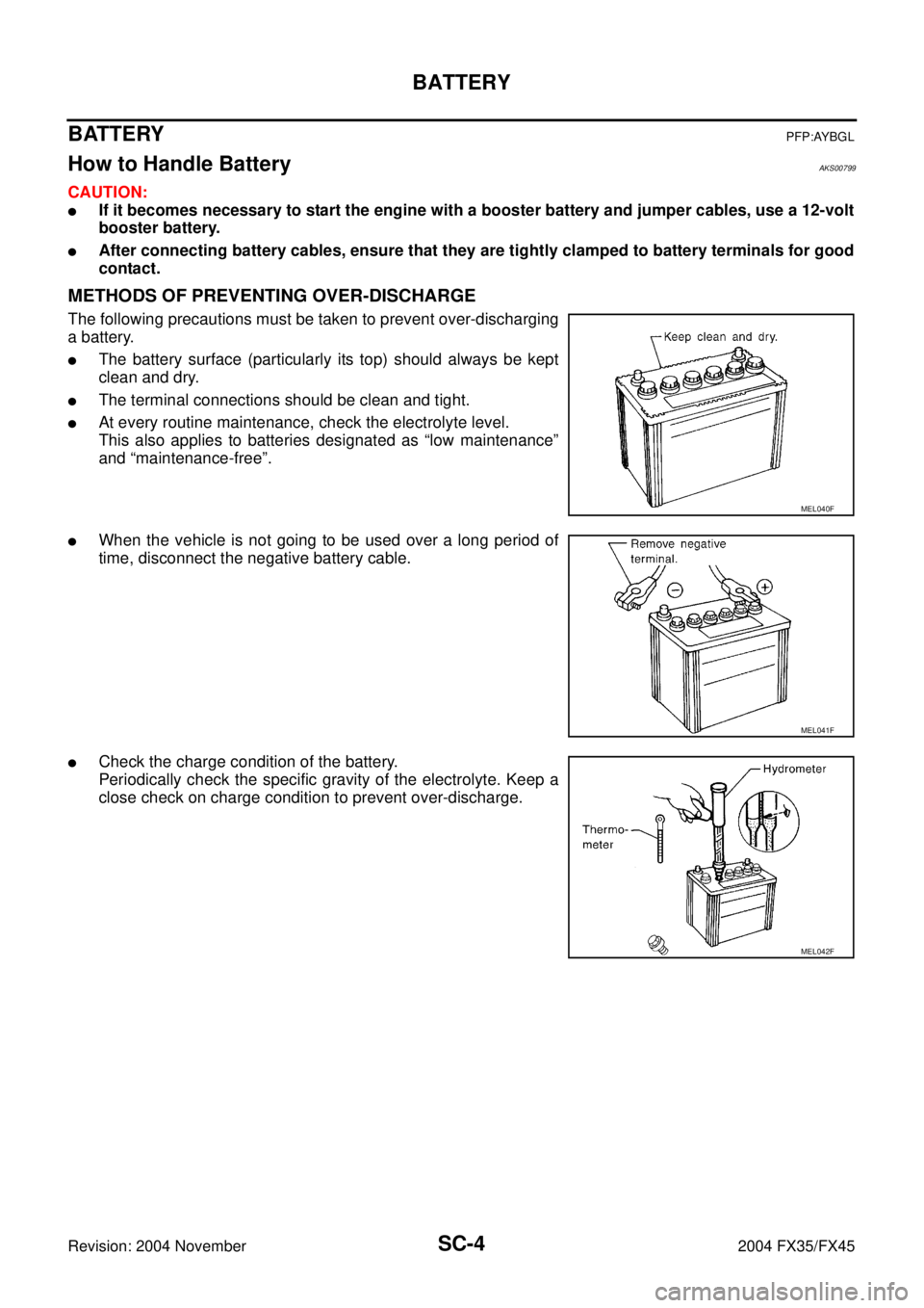
METHODS OF PREVENTING OVER-DISCHARGE
The following precautions must be taken to prevent over-discharging
a battery.
�The battery surface (particularly its top) should always be kept
clean and dry.
�The terminal connections should be clean and tight.
�At every routine maintenance, check the electrolyte level.
This also applies to batteries designated as “low maintenance”
and “maintenance-free”.
�When the vehicle is not going to be used over a long period of
time, disconnect the negative battery cable.
�Check the charge condition of the battery.
Periodically check the specific gravity of the electrolyte. Keep a
close check on charge condition to prevent over-discharge.
MEL040F
MEL041F
MEL042F
 “AIR BAG” and “SEAT
BELT PRE-TENSIONER")