Page 3248 of 4449
REAR WINDOW DEFOGGER
GW-89
C
D
E
F
G
H
J
K
L
MA
B
GW
Revision: 2004 November 2004 FX35/FX45
SchematicAIS004R2
TIWM0357E
Page 3249 of 4449
GW-90
REAR WINDOW DEFOGGER
Revision: 2004 November 2004 FX35/FX45
Wiring Diagram —DEF— AIS004R3
TIWM0358E
Page 3250 of 4449
REAR WINDOW DEFOGGER
GW-91
C
D
E
F
G
H
J
K
L
MA
B
GW
Revision: 2004 November 2004 FX35/FX45
TIWM0359E
Page 3251 of 4449
GW-92
REAR WINDOW DEFOGGER
Revision: 2004 November 2004 FX35/FX45
TIWM0360E
Page 3252 of 4449
REAR WINDOW DEFOGGER
GW-93
C
D
E
F
G
H
J
K
L
MA
B
GW
Revision: 2004 November 2004 FX35/FX45
TIWM0361E
Page 3253 of 4449

GW-94
REAR WINDOW DEFOGGER
Revision: 2004 November 2004 FX35/FX45
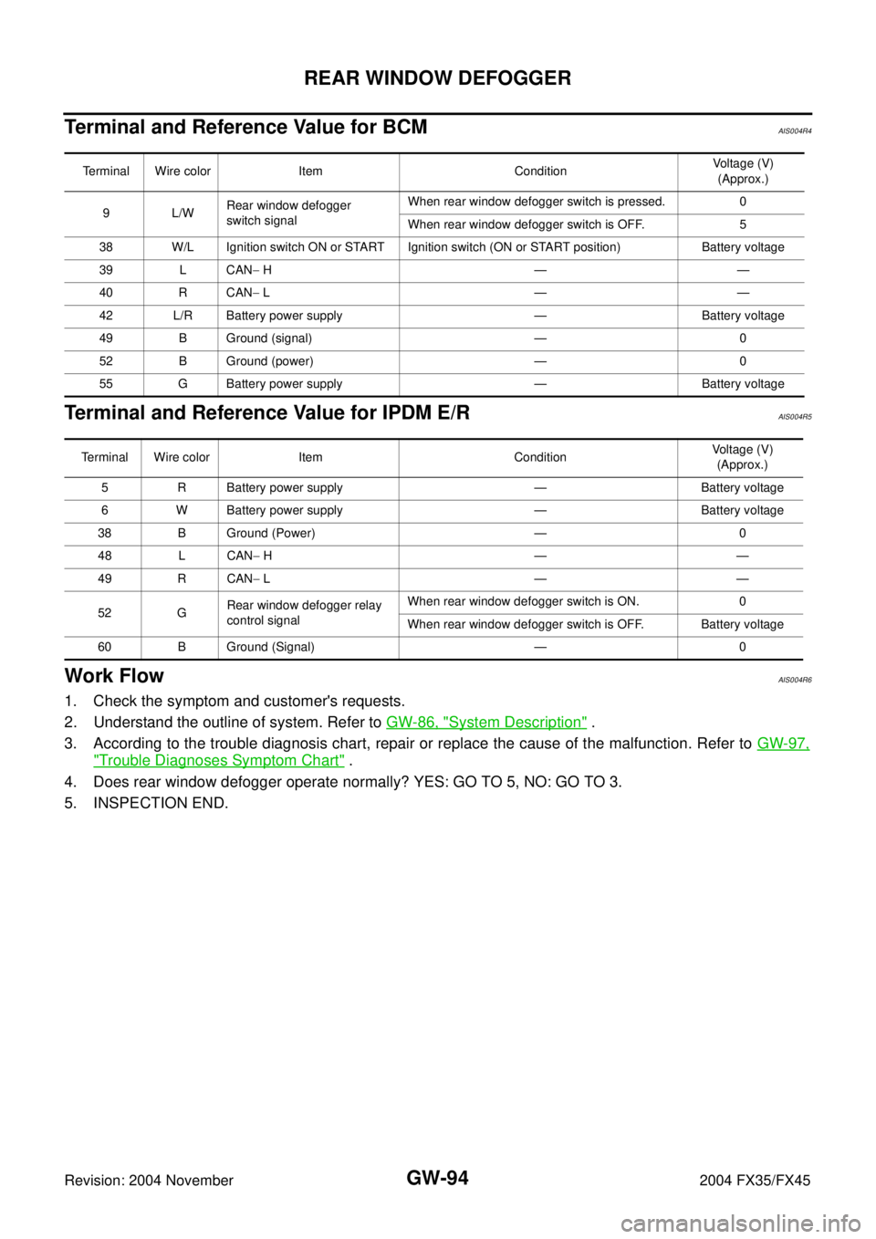
Terminal and Reference Value for BCMAIS004R4
Terminal and Reference Value for IPDM E/RAIS004R5
Work FlowAIS004R6
1. Check the symptom and customer's requests.
2. Understand the outline of system. Refer to GW-86, "
System Description" .
3. According to the trouble diagnosis chart, repair or replace the cause of the malfunction. Refer to GW-97,
"Trouble Diagnoses Symptom Chart" .
4. Does rear window defogger operate normally? YES: GO TO 5, NO: GO TO 3.
5. INSPECTION END.
Terminal Wire color Item ConditionVoltage (V)
(Approx.)
9L/WRear window defogger
switch signalWhen rear window defogger switch is pressed. 0
When rear window defogger switch is OFF. 5
38 W/L Ignition switch ON or START Ignition switch (ON or START position) Battery voltage
39 L CAN− H——
40 R CAN− L——
42 L/R Battery power supply — Battery voltage
49 B Ground (signal) — 0
52 B Ground (power) — 0
55 G Battery power supply — Battery voltage
Terminal Wire color Item ConditionVoltage (V)
(Approx.)
5 R Battery power supply — Battery voltage
6 W Battery power supply — Battery voltage
38 B Ground (Power) — 0
48 L CAN− H——
49 R CAN− L——
52 GRear window defogger relay
control signalWhen rear window defogger switch is ON. 0
When rear window defogger switch is OFF. Battery voltage
60 B Ground (Signal) — 0
Page 3254 of 4449
REAR WINDOW DEFOGGER
GW-95
C
D
E
F
G
H
J
K
L
MA
B
GW
Revision: 2004 November 2004 FX35/FX45
CONSULT-II Inspection ProcedureAIS004R7
CAUTION:
If CONSULT-II is used with no connection of CONSULT-II CONVERTER, malfunctions might be
detected in self-diagnosis depending on control unit which carry out CAN communication.
1. Turn ignition switch “OFF”.
2. Connect “CONSULT-II” and CONSULT-II CONVERTER to data
link connector.
3. Turn ignition switch “ON”.
4. Touch “START (NISSAN BASED VHCL)”.
5. Touch “BCM”.
If “BCM” is not indicated, go to GI-40
, “CONSULT-II Date Link
Connector (DLC) Circuit”
6. Touch “REAR DEFOGGER”.
PBIB1503E
MBIB0233E
LIIA0033E
LIIA0153E
Page 3255 of 4449
GW-96
REAR WINDOW DEFOGGER
Revision: 2004 November 2004 FX35/FX45
7. Select diagnosis mode,“DATA MONITOR” and “ACTIVE TEST”
are available.
DATA MONITOR
Display Item List
ACTIVE TEST
Display Item List
SEL322W
Monitor item Content
REAR DEF SW Displays “Press (ON)/others (OFF)” status determined with the rear window defogger switch.
IGN ON SW Displays “IGN (ON)/OFF” status determined with the ignition switch signal.
Test item Content
REAR DEFOGGER Gives a drive signal to the rear window defogger relay to activate it.