Page 4325 of 4449

TF-24
TROUBLE DIAGNOSIS
Revision: 2004 November 2004 FX35/FX45
ACTIVE TEST MODE
Description
Use this mode to determine and identify the details of a malfunction based on self-diagnostic results or data
monitor. AWD control unit gives drive signal to actuator with receiving command from CONSULT-II to check
operation of actuator.
Test Item
CAUTION:
Do not continuously energize for a long time.
AWD CONTROL UNIT PART NUMBER
Ignore the AWD control unit part number displayed in the “ECU PART NUMBER”.
Refer to parts catalog to order the AWD control unit.
Test item Condition Description
ETS S/V
(Detects AWD solenoid valve)
�Vehicle stopped
�Engine running
�No DTC detected
�Change command current value to AWD solenoid, and then change driv-
ing mode. (Monitor value is normal if it is within approximately ±10% of
command value.)
Qu: Increase current value in increments of 0.20A
Qd: Decrease current value in increments of 0.20A
UP: Increase current value in increments of 0.02A
DOWN: Decrease current value in increments of 0.02A
Page 4398 of 4449

FRONT WIPER AND WASHER SYSTEM
WW-7
C
D
E
F
G
H
I
J
L
MA
B
WW
Revision: 2004 November 2004 FX35/FX45
FAIL-SAFE FUNCTION
IPDM E/R includes a fail-safe function to prevent malfunction of electrical components controlled by CAN com-
munications in CAN communications occurs.
When fail-safe status is initiated, IPDM E/R remains in steady unit signals are received.
COMBINATION SWITCH READING FUNCTION
Description
�BCM reads combination switch (wiper) status, and controls related systems such as head lamps and wip-
ers, according to the results.
�BCM reads information of a maximum of 20 switches by combining five output terminals (OUTPUT 1-5)
and five input terminals (INPUT 1-5).
Operation Description
�BCM activates transistors of output terminals (OUTPUT 1-5) periodically and, and allows current to flow in
turn.
�If any (1 or more) switches are turned ON, circuit of output terminals (OUTPUT 1-5) and input terminals
(INPUT 1-5) becomes active.
�At this time, transistors of output terminals (OUTPUT 1-5) are activated to allow current to flow. When volt-
age of input terminals (INPUT 1-5) corresponding to that switch changes, interface in BCM detects volt-
age change, and BCM determines that switch is ON.
SKIA4958E
Page 4399 of 4449
WW-8
FRONT WIPER AND WASHER SYSTEM
Revision: 2004 November 2004 FX35/FX45
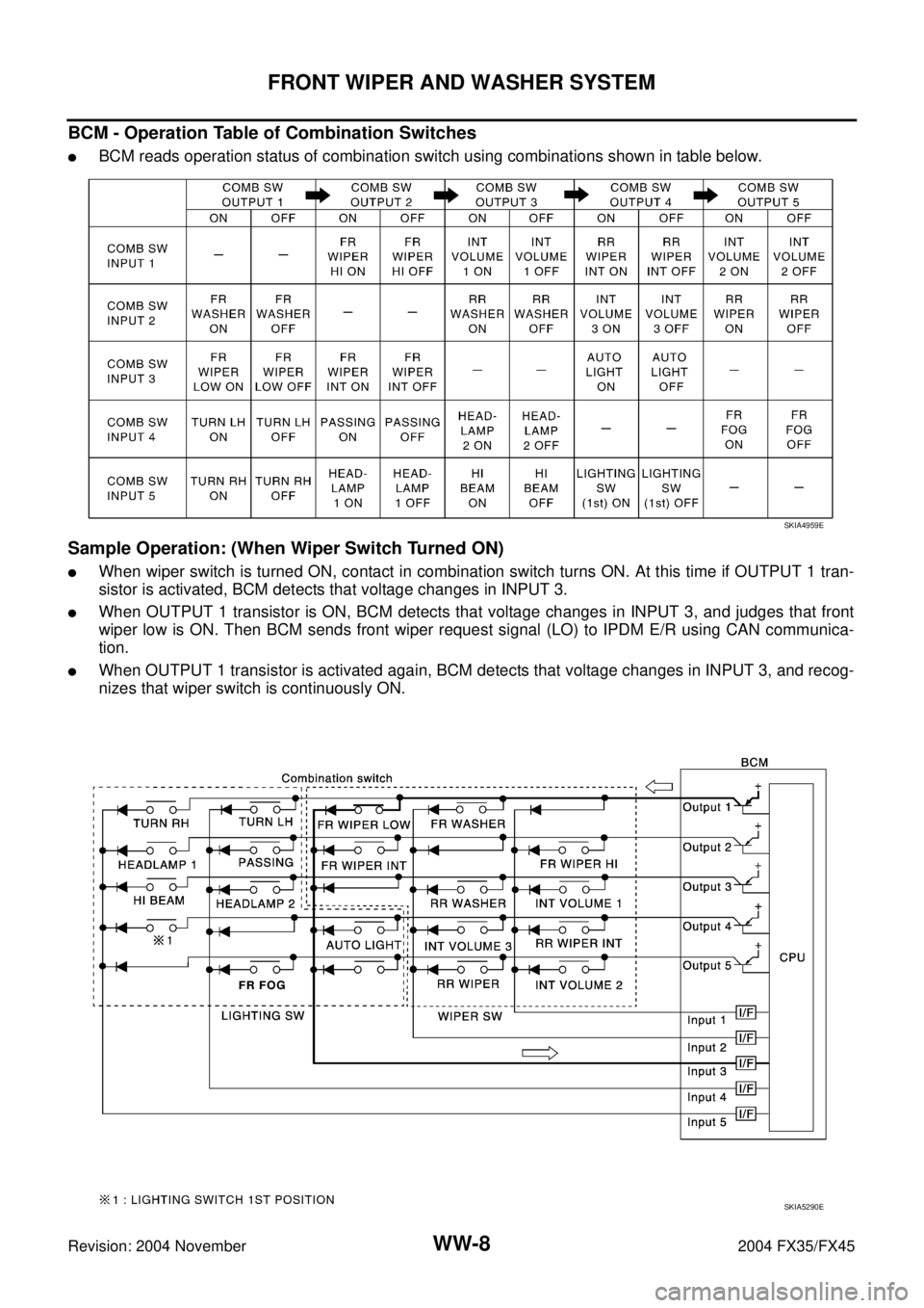
BCM - Operation Table of Combination Switches
�BCM reads operation status of combination switch using combinations shown in table below.
Sample Operation: (When Wiper Switch Turned ON)
�When wiper switch is turned ON, contact in combination switch turns ON. At this time if OUTPUT 1 tran-
sistor is activated, BCM detects that voltage changes in INPUT 3.
�When OUTPUT 1 transistor is ON, BCM detects that voltage changes in INPUT 3, and judges that front
wiper low is ON. Then BCM sends front wiper request signal (LO) to IPDM E/R using CAN communica-
tion.
�When OUTPUT 1 transistor is activated again, BCM detects that voltage changes in INPUT 3, and recog-
nizes that wiper switch is continuously ON.
SKIA4959E
SKIA5290E
Page 4417 of 4449

WW-26
FRONT WIPER AND WASHER SYSTEM
Revision: 2004 November 2004 FX35/FX45
Front Wiper Interval Time Is Not Controlled by Vehicle SpeedAKS007A1
1. CHECK FUNCTION OF COMBINATION METER
Confirm that speedometer operates normally.
Does the front wiper operate normally?
YES >> GO TO 2.
NO >> Combination meter vehicle speed system malfunction. GO TO DI-17, "
Vehicle Speed Signal
Inspection" .
2. CHECK CAN COMMUNICATION BETWEEN BCM AND COMBINATION METER
Select “BCM” on CONSULT-II, and perform self-diagnosis for
“BCM”.
Displayed self
-diagnosis results
NO DTC>>Replace BCM. Refer to BCS-15, "Removal and Installa-
tion of BCM" .
CAN COMM CIRCUIT>>Check CAN communication line of BCM.
GO TO BCS-14, "
CAN Communication Inspection Using
CONSULT-II (Self-Diagnosis)" .
Front Wiper Intermittent Operation Switch Position Cannot Be AdjustedAKS007YW
1. CHECK COMBINATION SWITCH INPUT SIGNAL
Select “BCM” on CONSULT-II. With “WIPER” data monitor, make
sure “INT VOLUME” changes in order from 1 to 7 according to oper-
ation of the intermittent switch dial position.
OK or NG
OK >> Replace BCM. Refer to LT- 11 3 , "Combination Switch
Inspection" .
NG >> Replace wiper switch.
Wipers Do Not Wipe When Front Washer OperatesAKS00575
1. CHECK CIRCUIT BETWEEN COMBINATION SWITCH AND BCM
Select “BCM” on CONSULT-II. With “WIPER” on “DATA MONITOR”,
make sure “FR WASHER SW” turns ON-OFF according to operation
of front washer switch.
OK or NG
OK >> Replace BCM. Refer to BCS-15, "Removal and Installa-
tion of BCM" .
NG >> Replace wiper switch.
SKIA1039E
SKIA4234E
When front wiper switch
washer position: FR WASHER SW ON
SKIA5300E