Page 312 of 4449
A/T SHIFT LOCK SYSTEM
AT-235
D
E
F
G
H
I
J
K
L
MA
B
AT
Revision: 2004 November 2004 FX35/FX45
A/T SHIFT LOCK SYSTEMPFP:34950
DescriptionACS002RT
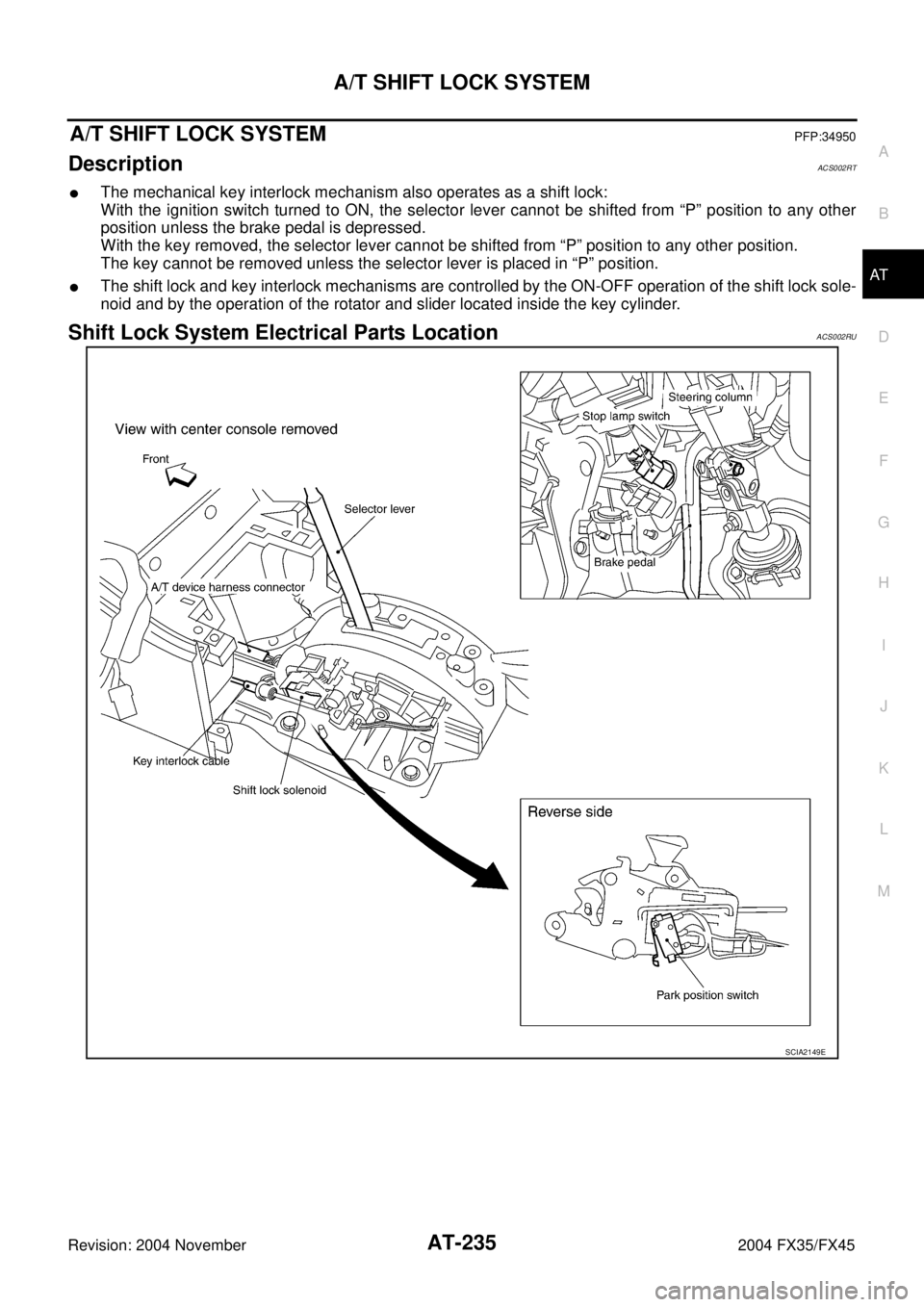
�The mechanical key interlock mechanism also operates as a shift lock:
With the ignition switch turned to ON, the selector lever cannot be shifted from “P” position to any other
position unless the brake pedal is depressed.
With the key removed, the selector lever cannot be shifted from “P” position to any other position.
The key cannot be removed unless the selector lever is placed in “P” position.
�The shift lock and key interlock mechanisms are controlled by the ON-OFF operation of the shift lock sole-
noid and by the operation of the rotator and slider located inside the key cylinder.
Shift Lock System Electrical Parts LocationACS002RU
SCIA2149E
Page 314 of 4449

A/T SHIFT LOCK SYSTEM
AT-237
D
E
F
G
H
I
J
K
L
MA
B
AT
Revision: 2004 November 2004 FX35/FX45
Diagnostic ProcedureACS002RW
SYMPTOM 1:
�Selector lever cannot be moved from “P” position with key in ON position and brake pedal
applied.
�Selector lever can be moved from “P” position with key in ON position and brake pedal released.
�Selector lever can be moved from “P” position when key is removed from key cylinder.
SYMPTOM 2:
�Ignition key cannot be removed when selector lever is set to “P” position.
�Ignition key can be removed when selector lever is set to any position except “P” position.
1. CHECK KEY INTERLOCK CABLE
Check the key interlock cable for damage.
OK or NG
OK >> GO TO 2.
NG >> Repair key interlock cable. Refer to AT- 2 3 9 , "
KEY INTERLOCK CABLE" .
2. CHECK SELECTOR LEVER POSITION
Check the selector lever position for damage.
OK or NG
OK >> GO TO 3.
NG >> Adjustment control linkage. Refer to AT- 2 3 4 , "
Adjustment of A/T Position" .
3. CHECK SHIFT LOCK SOLENOID AND PARK POSITION SWITCH
1. Connect A/T device harness connector.
2. Turn ignition switch “ON”.
3. Selector lever is set in “P” position.
4. Check operation sound.
OK or NG
OK >>INSPECTION END
NG >> GO TO 4.
4. CHECK POWER SOURCE
1. Turn ignition switch “ON”. (Do not start engine.)
2. Check the voltage between A/T device harness connector M67
terminal 1(G/R) and ground. Refer to AT- 2 3 6 , "
Wiring Diagram
— AT — SHIFT" .
OK or NG
OK >> GO TO 7.
NG >> GO TO 5.
Condition Brake pedal Operation sound
When ignition switch is turned to
“ON” position and selector lever
is set in “P” position.Depressed Yes
Released No
Condition Brake pedal Data (Approx.)
When ignition switch is turned to
“ON” position.Depressed Battery voltage
Released 0V
SCIA2122E
Page 315 of 4449

AT-238
A/T SHIFT LOCK SYSTEM
Revision: 2004 November 2004 FX35/FX45
5. CHECK STOP LAMP SWITCH
1. Turn ignition switch “OFF”.
2. Disconnect stop lamp switch harness connector.
3. Check continuity between stop lamp switch harness connector
E210 terminals 3(G) and 4(OR). Refer to AT- 2 3 6 , "
Wiring Dia-
gram — AT — SHIFT" .
Check stop lamp switch after adjusting brake pedal — refer to
BR-6, "
BRAKE PEDAL" .
OK or NG
OK >> GO TO 6.
NG >> Repair or replace damaged parts.
6. DETECT MALFUNCTIONING ITEM
Check the following items. If any items are damaged, repair or replace damaged parts.
�Harness for short or open between ignition switch and stop lamp switch harness terminal 3(G).
�Harness for short or open between stop lamp switch harness terminal 4(O/R) and A/T device harness ter-
minal 1(G/R).
�10A fuse [No.12, located in the fuse block (J/B)].
�Ignition switch. Refer to PG-3, "POWER SUPPLY ROUTING CIRCUIT" .
OK or NG
OK >>INSPECTION END
NG >> Repair or replace damaged parts.
7. CHECK GROUND CIRCUIT
1. Turn ignition switch “OFF”.
2. Disconnect A/T device harness connector.
3. Check continuity between A/T device harness connector M67
terminal 2(B) and ground.
4. Connect A/T device harness connector.
OK or NG
OK >> Replace shift lock solenoid or park position switch
assembly.
NG >> Repair open circuit or short to ground or short to power
in harness or connectors.
Condition Continuity
When brake pedal is depressed Yes
When brake pedal is released No
SCIA2126E
Continuity should exist.
SCIA2125E
Page 352 of 4449
OVERHAUL
AT-275
D
E
F
G
H
I
J
K
L
MA
B
AT
Revision: 2004 November 2004 FX35/FX45
1. O-ring 2. Oil pump cover 3. O-ring
4. Oil pump housing 5. Self-sealing bolt 6. Torque converter
7. Converter housing 8. Oil pump housing oil seal 9. Bearing race
10. Needle bearing 11. O-ring 12. Front carrier assembly
13. Snap ring 14. Front sun gear 15. 3rd one-way clutch
16. Snap ring 17. Bearing race 18. Needle bearing
19. Seal ring 20. Input clutch assembly 21. Needle bearing
22. Rear internal gear 23. Brake band 24. Mid carrier assembly
25. Needle bearing 26. Bearing race 27. Rear carrier assembly
28. Needle bearing 29. Mid sun gear 30. Seal ring
31. Rear sun gear 32. 1st one-way clutch 33. Snap ring
34. Needle bearing 35. High and low reverse clutch hub 36. Snap ring
37. Bearing race 38. Needle bearing
Page 353 of 4449
AT-276
OVERHAUL
Revision: 2004 November 2004 FX35/FX45
1. Needle bearing 2. Bearing race 3. High and low reverse clutch assem-
bly
4. Needle bearing 5. Direct clutch assembly 6. Reverse brake dish plate
SCIA5043E
Page 354 of 4449
OVERHAUL
AT-277
D
E
F
G
H
I
J
K
L
MA
B
AT
Revision: 2004 November 2004 FX35/FX45
7. Reverse brake driven plate 8. N-spring 9. Reverse brake drive plate
10. Reverse brake retaining plate 11. Snap ring 12. Lip seal
13. D-ring 14. Reverse brake piston 15. Return spring
16. Spring retainer 17. Snap ring
Page 366 of 4449
DISASSEMBLY
AT-289
D
E
F
G
H
I
J
K
L
MA
B
AT
Revision: 2004 November 2004 FX35/FX45
14. Loosen lock nut and remove band servo anchor end pin from
transmission case.
15. Remove brake band from transmission case.
�To prevent brake linings from cracking or peeling, do not
stretch the flexible band unnecessarily. When removing
the brake band, always secure it with a clip as shown in
the figure at right.
Leave the clip in position after removing the brake band.
�Check brake band facing for damage, cracks, wear or
burns.
16. Remove mid carrier assembly and rear carrier assembly as a
unit.
17. Remove mid carrier assembly from rear carrier assembly.
SCIA5016E
SCIA2580E
SAT655
SCIA5017E
SCIA5697E
Page 368 of 4449
DISASSEMBLY
AT-291
D
E
F
G
H
I
J
K
L
MA
B
AT
Revision: 2004 November 2004 FX35/FX45
23. Remove high and low reverse clutch assembly from direct clutch
assembly.
CAUTION:
Make sure that needle bearing is installed to the high and
low reverse clutch assembly edge surface.
24. Remove direct clutch assembly from reverse brake.
25. Remove needle bearing from drum support.
26. Remove snap ring from A/T assembly harness connector.
27. Push A/T assembly harness connector.
CAUTION:
Be careful not to damage connector.
SCIA2306E
SCIA5019E
SCIA5198E
SCIA5021E
SCIA5022E