Page 3021 of 4449
![INFINITI FX35 2004 Service Manual FAX-12
[AWD]
FRONT DRIVE SHAFT
Revision: 2004 November 2004 FX35/FX45
FRONT DRIVE SHAFTPFP:39100
Removal and Installation (Left Side)ADS000ON
REMOVAL
1. Remove tire from vehicle with power tool.
2. Re](/manual-img/42/57021/w960_57021-3020.png "INFINITI FX35 2004 Service Manual FAX-12
[AWD]
FRONT DRIVE SHAFT
Revision: 2004 November 2004 FX35/FX45
FRONT DRIVE SHAFTPFP:39100
Removal and Installation (Left Side)ADS000ON
REMOVAL
1. Remove tire from vehicle with power tool.
2. Re")
FAX-12
[AWD]
FRONT DRIVE SHAFT
Revision: 2004 November 2004 FX35/FX45
FRONT DRIVE SHAFTPFP:39100
Removal and Installation (Left Side)ADS000ON
REMOVAL
1. Remove tire from vehicle with power tool.
2. Remove undercover with power tool.
3. Remove cotter pin. Then remove lock nut from drive shaft with power tool.
4. Remove wheel sensor harness from strut assembly. Refer to BRC-57, "
WHEEL SENSORS" .
CAUTION:
Do not pull on wheel sensor harness.
5. Remove brake hose lock plate. Then remove brake hose from strut assembly. Refer to BR-11, "
BRAKE
PIPING AND HOSE" .
6. Remove fixing bolts and nuts between strut assembly and steering knuckle with power tool.
7. Remove drive shaft from steering knuckle.
CAUTION:
When removing drive shaft, do not apply an excessive angle to drive shaft joint. Also be careful
not to excessively extend slide joint.
8. Remove fixing bolt of front final drive side assembly drive shaft with power tool, then remove drive shaft
from vehicle.
INSPECTION AFTER REMOVAL
�Move joint up/down, left /right, and in the axial direction. Check for any rough movement or significant
looseness.
�Check boot for cracks or other damage, and also for grease
leakage.
�If a trouble is found, disassemble drive shaft, and then replace
with new one.
INSTALLATION
�Refer to FA X - 1 2 , "Removal and Installation (Left Side)" for tightening torque. Install in the reverse order of
removal.
NOTE:
Refer to component parts location and do not reuse non-reusable parts.
�Check the following item after service.
–Installation condition of wheel sensor harness
1. Cotter pin 2. Washer
SDIA1441E
SDIA1046J
Page 3022 of 4449
![INFINITI FX35 2004 Service Manual FRONT DRIVE SHAFT
FAX-13
[AWD]
C
E
F
G
H
I
J
K
L
MA
B
FA X
Revision: 2004 November 2004 FX35/FX45
Removal and Installation (Right Side)ADS000OO
REMOVAL
1. Remove tire from vehicle with power tool.
2.](/manual-img/42/57021/w960_57021-3021.png "INFINITI FX35 2004 Service Manual FRONT DRIVE SHAFT
FAX-13
[AWD]
C
E
F
G
H
I
J
K
L
MA
B
FA X
Revision: 2004 November 2004 FX35/FX45
Removal and Installation (Right Side)ADS000OO
REMOVAL
1. Remove tire from vehicle with power tool.
2.")
FRONT DRIVE SHAFT
FAX-13
[AWD]
C
E
F
G
H
I
J
K
L
MA
B
FA X
Revision: 2004 November 2004 FX35/FX45
Removal and Installation (Right Side)ADS000OO
REMOVAL
1. Remove tire from vehicle with power tool.
2. Remove undercover with power tool.
3. Remove cotter pin. Then remove lock nut from drive shaft with power tool.
4. Remove wheel sensor harness from strut assembly. Refer to BRC-57, "
WHEEL SENSORS" .
CAUTION:
Do not pull on wheel sensor harness.
5. Remove brake hose lock prate. Then remove brake hose from strut assembly. Refer to BR-11, "
BRAKE
PIPING AND HOSE" .
6. Remove fixing bolts and nuts between strut assembly and steering knuckle with power tool.
7. Remove drive shaft from steering knuckle.
CAUTION:
When removing drive shaft, do not apply an excessive angle to drive shaft joint. Also be careful
not to excessively extend slide joint.
8. Pry off drive shaft from front final drive assembly side as shown
in the figure.
INSPECTION AFTER REMOVAL
�Move joint up/down, left/right, and in the axial direction. Check for any rough movement or significant
looseness.
�Check boot for cracks or other damage, and also for grease
leakage.
�If a trouble is found, disassemble drive shaft, and then replace
with new one.
1. Cotter pin 2. Washer
SDIA1442E
SDIA1489E
SFA108A
Page 3045 of 4449
ADS000N9
REMOVAL
1. Remove the three engine mounting brack")
FFD-10
FRONT FINAL DRIVE ASSEMBLY
Revision: 2004 November 2004 FX35/FX45
FRONT FINAL DRIVE ASSEMBLYPFP:38500
Removal and Installation (VQ35DE)ADS000N9
REMOVAL
1. Remove the three engine mounting bracket upper bolts.
2. Remove the right bank catalytic converter. Refer to EM-26, "
Removal and Installation" .
3. Remove the stabilizer assembly. Refer to FSU-16, "
STABILIZER BAR" .
4. Remove the steering gearbox mounting bolts. Refer to PS-19, "
POWER STEERING GEAR AND LINK-
AGE" .
5. Remove the front drive shaft BOTH. Refer to FAX-12, "
FRONT DRIVE SHAFT" .
6. Remove the side shaft assembly.
7. Remove the front propeller shaft. Refer to PR-4, "
FRONT PROPELLER SHAFT" .
8. Remove the front suspension member. Refer to FSU-17, "
FRONT SUSPENSION MEMBER" .
9. Remove the differential breather hose clamp bolt. Refer to FFD-12, "
REMOVAL AND INSTALLATION
(VQ35DE)" .
10. Remove the mounting bolts and front final drive assembly from the vehicle.
INSTALLATION
Install in the reverse order of removal.
CAUTION:
�When installing the side shaft, apply multi-purpose grease to contact surface of side shaft and
side shaft oil seal.
�After installation, check the final drive oil level. Refer to
SDIA1586E
1. Insulator 2. Engine mounting bracket 3. Breather joint
4. Breather hose 5. Breather tube 6. Propeller shaft
7. Side shaft 8. Front final drive assembly
Page 3046 of 4449
ADS000OE
REMOVAL
1. Remove the right bank catalytic converter. Refe")
FRONT FINAL DRIVE ASSEMBLY
FFD-11
C
E
F
G
H
I
J
K
L
MA
B
FFD
Revision: 2004 November 2004 FX35/FX45
Removal and Installation (VK45DE)ADS000OE
REMOVAL
1. Remove the right bank catalytic converter. Refer to EM-178, "Removal and Installation" .
2. Remove the stabilizer assembly. Refer to FSU-16, "
STABILIZER BAR" .
3. Remove the steering gearbox mounting bolts. Refer to PS-19, "
POWER STEERING GEAR AND LINK-
AGE" .
4. Remove the front drive shaft both. Refer to FAX-12, "
FRONT DRIVE SHAFT" .
5. Remove the side shaft assembly.
6. Remove the front propeller shaft. Refer to PR-4, "
FRONT PROPELLER SHAFT" .
7. Remove the front suspension member. Refer to FSU-17, "
FRONT SUSPENSION MEMBER" .
8. Remove the engine wire harness clamp bolts from front final drive.
9. Remove the differential breather hose clamp bolt. Refer to FFD-13, "
REMOVAL AND INSTALLATION
(VK45DE)" .
10. Remove the mounting bolts and front final drive assembly from the vehicle.
INSTALLATION
Install in the reverse order of removal.
CAUTION:
�When installing side shaft, apply multi-purpose grease to contact surface of side shaft and side
shaft oil seal.
�After installation, check the final drive oil level. Refer to
SDIA1587E
1. Breather joint 2. Front final drive assembly 3. Side shaft
4. Propeller shaft 5. Breather tube 6. Breather hose
Page 3089 of 4449
FSU-4
PREPARATION
Revision: 2004 November 2004 FX35/FX45
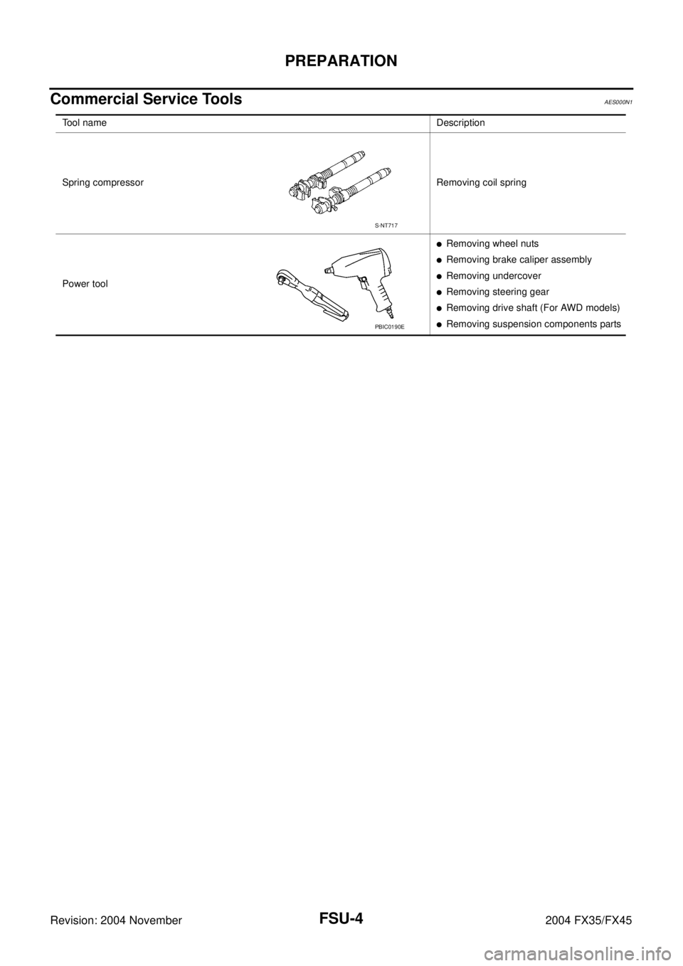
Commercial Service ToolsAES000N1
Tool nameDescription
Spring compressor Removing coil spring
Power tool
�Removing wheel nuts
�Removing brake caliper assembly
�Removing undercover
�Removing steering gear
�Removing drive shaft (For AWD models)
�Removing suspension components parts
S-NT717
PBIC0190E
Page 3094 of 4449

FRONT SUSPENSION ASSEMBLY
FSU-9
C
D
F
G
H
I
J
K
L
MA
B
FSU
Revision: 2004 November 2004 FX35/FX45
Removal and InstallationAES000N6
REMOVAL
1. Set an engine slinger to engine, then suspend engine.
2. Remove tire from vehicle with power tool.
3. Remove brake caliper with power tool. Hang it in a place where it will not interfere with work. Refer to BR-
20, "FRONT DISC BRAKE" .
4. Remove brake hose lock plate. Then remove brake hose from
strut assembly.
5. Remove disc rotor.
6. Remove wheel sensor harness from strut assembly.
CAUTION:
Do not pull on wheel sensor harness.
7. Remove undercover with power tool.
8. Remove front cross bar.
9. Remove steering hydraulic piping bracket from front suspension
member. Refer to PS-41, "
HYDRAULIC LINE" .
10. Remove cotter pin at steering outer socket, then loosen mount-
ing nut.
11. Use a ball joint remover (SST) to remove steering outer socket
from steering knuckle. Be careful not to damage ball joint boot.
CAUTION:
Tighten temporarily mounting nut to prevent damage to
threads and to prevent ball joint remover (SST) from com-
ing off.
12. Remove mounting bolts of steering gear with power tool, then
hang steering gear on vehicle. Refer to PS-19, "
POWER
STEERING GEAR AND LINKAGE" .
13. Remove front final drive side of drive shaft with power tool. (For
AWD models) Refer to FAX-12, "
Removal and Installation (Left
Side)" , FA X - 1 3 , "Removal and Installation (Right Side)" .
14. Set jack under front suspension member.
15. Remove fixing bolts and nuts between strut assembly and steering knuckle with power tool.
1. Strut upper plate 2. Strut spacer 3. Mounting insulator
4. Mounting insulator bracket 5. Mounting bearing 6. Spring upper seat
7. Spring upper rubber seat 8. Coil spring 9. Spring lower rubber seat
10. Bound bumper 11. Strut 12. Steering knuckle
13. Front suspension member 14. Transverse link 15. Stabilizer bar
16. Stabilizer bushing 17. Stabilizer clamp 18. Stabilizer connecting rod
19. Front cross bar 20. Cotter pin
SEIA0328E
SEIA0329E
SDIA1434E
Page 3095 of 4449

FSU-10
FRONT SUSPENSION ASSEMBLY
Revision: 2004 November 2004 FX35/FX45
16. Remove stabilizer connecting rod upper nut with power tool,
separate stabilizer connecting rod and strut assembly.
17. Remove mounting nuts between engine mounting insulator and
front suspension member.
18. Remove mounting bolts which are at the back of transverse link
(mounting part with body) with power tool, separate transverse
link.
19. Remove mounting nuts between front suspension member and
body with power tool.
20. Move jack down slowly to remove front suspension member,
transverse link, stabilizer bar, drive shaft (For AWD models) and
steering knuckle from vehicle as a unit.
21. Remove transverse link from steering knuckle. Refer to FSU-14,
"TRANSVERSE LINK" .
INSTALLATION
�Refer to FSU-8, "Components" for tightening torque. Install in the reverse order of removal.
NOTE:
Refer to component parts location and do not reuse non-reusable parts.
�After removing/installing or replacing suspension components and steering components, check wheel
alignment. Refer to FSU-6, "
Wheel Alignment Inspection" .
�After adjusting wheel alignment, adjust neutral position of steering angle sensor. Refer to BRC-6, "Adjust-
ment of Steering Angle Sensor Neutral Position" .
�Check the following item after service.
–Installation condition of wheel sensor harness.
SEIA0330E
SEIA0331E
Page 3096 of 4449

COIL SPRING AND STRUT
FSU-11
C
D
F
G
H
I
J
K
L
MA
B
FSU
Revision: 2004 November 2004 FX35/FX45
COIL SPRING AND STRUTPFP:55302
Removal and InstallationAES000N7
REMOVAL
1. Remove tire from vehicle with power tool.
2. Remove brake hose lock plate. Then remove brake hose from
strut assembly.
3. Remove wheel sensor harness from strut assembly.
CAUTION:
Do not pull wheel sensor harness.
4. Remove stabilizer connecting rod upper nut with power tool,
separate stabilizer connecting rod and strut assembly.
5. Remove fixing bolts and nuts between strut assembly and steer-
ing knuckle with power tool.
6. Remove mounting nuts on mounting insulator bracket with
power tool, then remove strut upper plate, strut spacer and strut
from vehicle.
INSTALLATION
�Refer to FSU-8, "Components" for tightening torque. Install in the reverse order of removal.
NOTE:
Refer to component parts location and do not reuse non-reusable parts.
�After removing/installing or replacing suspension components, check wheel alignment. Refer to FSU-6,
"Wheel Alignment Inspection" .
�After adjusting wheel alignment, adjust neutral position of steering angle sensor. Refer to BRC-6, "Adjust-
ment of Steering Angle Sensor Neutral Position" .
�Check the following item after service.
–Installation condition of wheel sensor harness.
SEIA0328E
SEIA0329E
SEIA0330E