Page 180 of 208
6- 22 DO-IT-YOURSELF MAINTENANCE
!
4. Disconnect the power cord from the bulb
base in the back of the headlight.
HEF-225
HEF-2291FJB5036HEF-226
HEF-230
WARNING:This halogen bulb contains gas under pres-
sure and if impacted could shatter, result-
ing in flying fragments. Always wear eye
protection when servicing the bulb. Protect
the bulb against abrasions or scratches
and against liquids when lighted. Turn the
bulb on only when installing in a headlight.
Replace the headlight if damaged or cracked.
Keep the bulb out of the reach of children
and dispose of the used bulb with care.
5. Push the bulb spring for removing the head-
light bulb.
High Beam
Low Beam
High Beam
Low Beam
Page 181 of 208
DO-IT-YOURSELF MAINTENANCE 6- 23
HEF-227
6. Replace to the new bulb.
HEF-231
Low Beam
High BeamG270B01Y-AATFront turn signal Light
1. Take off the headlight module to remove
three bolts with a spanner.
HEF-221
HEF-222HEF-223
2. Disconnect the power code.3. Replace to the new bulb.
Page 182 of 208
6- 24 DO-IT-YOURSELF MAINTENANCE
G270D01Y-AATRear Combination Light
1. Remove the cover with a (+) driver.
2. Replace to the new bulb.
HEF-242
HEF-220
(1)
(2)
(3)(1) Trun signal light
(2) Stop/Tail light
(3) Back-up light
G270E01Y-GATLuggage Compartment Light
1. Open the trunk lid.
2. Remove the cover with a (-) driver.
HEF-239G270E02L
HTB284
Screwdriver
3. Disconnect the power cord.
4. Replace to the new bulb.
Page 183 of 208
DO-IT-YOURSELF MAINTENANCE 6- 25
G270E01TB-GATSide Repeater
1. Push the cover toward the front of vehicle
and remove it.
2. Disconnect the power code.
G270E01A
HTB277G270G01TB-GAT
Interior Light (If installed)
1. Reomove the cover with a (-) driver.
HEF-232
HEF-233
2. Replace to the new bulb.
HTB278
3. Replace to the new Bulb.
Page 184 of 208

6- 26 DO-IT-YOURSELF MAINTENANCE
!
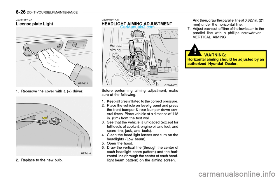
G290A05Y-AATHEADLIGHT AIMING ADJUSTMENT
Before performing aiming adjustment, make
sure of the following.
1. Keep all tires inflated to the correct pressure.
2. Place the vehicle on level ground and press
the front bumper & rear bumper down sev-
eral times. Place vehicle at a distance of 118
in. (3m) from the test wall.
3. See that the vehicle is unloaded (except for
full levels of coolant, engine oil and fuel, and
spare tire, jack, and tools).
4. Clean the head light lenses and turn on the
headlights (Low beam).
5. Open the hood.
6. Draw the vertical line (through the center of
each headlight beam pattern) and the hori-
zontal line (through the center of each head-
light beam pattern) on the aiming screen.And then, draw the parallel line at 0.827 in. (21
mm) under the horizontal line.
7. Adjust each cut-off line of the low beam to the
parallel line with a phillips screwdriver -
VERTICAL AIMING
WARNING:Horizontal aiming should be adjusted by an
authorized Hyundai Dealer.
G290A03Y
G270H01Y-GATLicense plate Light
1. Reomove the cover with a (+) driver.
2. Replace to the new bulb.
HEF-235
HEF-236
Vertical
aiming
Page 185 of 208
DO-IT-YOURSELF MAINTENANCE 6- 27
SPECIFICATION:
"H"
Horizontal center line of headlights from ground
:
Low Beam: 25.55 in. (649mm)
High Beam: 25.31 in. (643mm)
"W"
Distance between each headlight center :
Low Beam: 51.97 in. (1,320mm)
High Beam: 39.05 in. (992mm)
"L"
Distance between the headlights and the wall
that the lights are tested against : 118 in. (3,000
mm)G290B02Y-AATAdjustment After Headlight Assembly
Replacement
If the vehicle has had front body repair and the
headlight assembly has been replaced, the
headlight aiming should be checked using the
aiming screen as shown in the illustration. Turn
on the headlight switch.
1. Adjust headlights so that main axis of light is
parallel to center line of the body and is
aligned with point "P" shown in the illustration.
2. Dotted lines in the illustration show the center
of headlights.
G290B02Y-1
LW
H
HCut-off line
Ground
line
"P"
Horizontal line
0.827 in. (21 mm)Vertical line
Page 186 of 208
6- 28 DO-IT-YOURSELF MAINTENANCE
Part Name
Head Light (High/Low)
Map Light
Interior Light
Front Fog Light (If installed)
Turn signal Light/Front position Light
Side Mark Light
Front Door Edge LightWith Sunroof
Without Sunroof
G280A04Y-AAT
No.
1
2
3
4
5
6
7Wattage
55(H1)/55(H7)
5
5
10
55
28/8
5
5No.
8
9
10
11Wattage
3.2 (LED type)
5
27/8
27
27
5 Part Name
High Mounted Rear stop Light
Luggage Compartment Light
Rear Combination Light
Stop / Tail Light
Turn signal Light
Back up Light
License plate Light
1
G280A04Y
12389
45671011
(High)(Low)
Page 187 of 208

DO-IT-YOURSELF MAINTENANCE 6- 29
G200C03Y-GATJUNCTION BOX DESCRIPTION
Under hood junction box
Note:
Not all junction box description in this manual may be applicable to
your vehicle. It is accurate at the time of printing. When you inspect the
junction box on your vehicle, refer to the junction box label
DESCRIPTION
COND FAN
PWR WIND
ABS 2
IGN SW-1
ABS 1
IGN SW-2
RAD FAN MTR
FUEL PUMP
HD LP LO
ABS
INJECTOR
A/C COMPR
ATM RLY
ECU RLY
IG COIL
O2 SNSR
ECU
HORN
HEAD LP HI
HEAD LP WASH
DRL
FR FOG
HEAD LP LO RH
DIODE-1
SPARE
SPARE
SPARE
SPARE
DIODE-2
BLOWER
PWR FUSE-2
PWR AMP
SUNROOF
TAIL LP
PWR FUSE-1
ECU
RR HTDFUSE RATING
20A
40A
20A
30A
40A
30A
30A
20A
15A
10A
10A
10A
20A
30A
20A
15A
15A
10A
15A
20A
15A
15A
15A
-
30A
20A
15A
10A
-
30A
30A
20A
15A
20A
30A
10A
30APROTECTED COMPONENTS
Condenser fan
Power window
ABS
Ignition switch
ABS
Ignition switch
Radiator fan motor
Fuel pump
Headlights (LO)
ABS
Injector
Air-con compressor
ATM Relay
Engine control unit relay
Ignition coil
Oxygen sensor
Engine control unit
Horn
Headlights (HI)
-
DRL
Front fog lights
Headlight (Low)
Diode 1
Spare fuse
Spare fuse
Spare fuse
Spare fuse
Diode 2
Blower
Power fuse 2
Power amp
Sunroof
Tail lights
Power fuse 1
ECU
Rear window defroster
HEF-165C