2004 Hyundai H-1 (Grand Starex) heater
[x] Cancel search: heaterPage 11 of 273

1. Multi-function light switch
2. Seat warmer switch (If installed)
3. Horn/Driver's side airbag (If installed)
4. Rear heater switch (If installed)
5. Windshield wiper/Washer switch
6. Hazard warning switch
7. Front fog light switch (If installed)
8. 4WD Switch (If installed)
9. Rear fog light switch (If installed)
10. Rear window defroster switch
11. Passenger's side airbag (If installed)
12. Glove box13. Headlight leveling device switch (If installed)
14. ECT switch (Automatic transmission only)
15. Fuel-filler lid release lever
16. Hood release lever
17. Panel brightness control knob (Rheostat) (If installed)
18. Engine RPM adjustment knob (If installed)
19. Heater/Air conditioner control panel
20. Cigarette lighter
21. Ashtray
22. Drink holder
23. Audio system (If installed)
24. Digital clock (If installed)
CAUTION:
When installing the container of liquid air refresher inside a vehicle, do not place it near theinstrument cluster nor on the crash pad surface. If there is any leakage from the air refresher onto these areas (Instrument cluster, crash pad or air ventilator), it may damage these parts. If the liquid from air refresher does leak onto these areas, wash them with water immediately.
!
Page 13 of 273

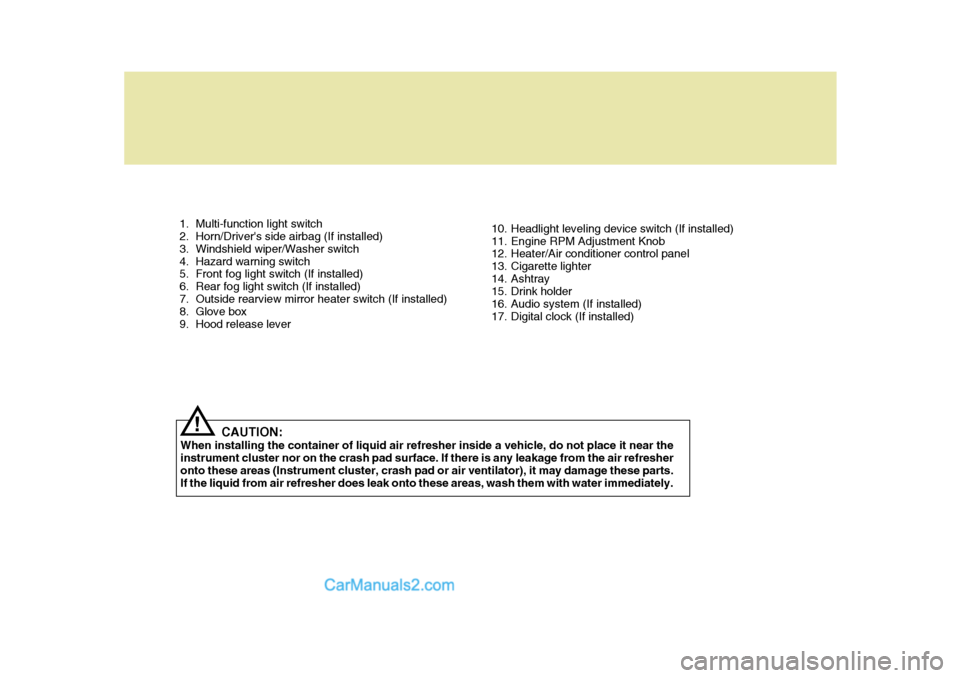
1. Multi-function light switch
2. Horn/Driver's side airbag (If installed)
3. Windshield wiper/Washer switch
4. Hazard warning switch
5. Front fog light switch (If installed)
6. Rear fog light switch (If installed)
7. Outside rearview mirror heater switch (If installed)
8. Glove box
9. Hood release lever10. Headlight leveling device switch (If installed)
11. Engine RPM Adjustment Knob
12. Heater/Air conditioner control panel
13. Cigarette lighter
14. Ashtray
15. Drink holder
16. Audio system (If installed)
17. Digital clock (If installed)
CAUTION:
When installing the container of liquid air refresher inside a vehicle, do not place it near theinstrument cluster nor on the crash pad surface. If there is any leakage from the air refresheronto these areas (Instrument cluster, crash pad or air ventilator), it may damage these parts. If the liquid from air refresher does leak onto these areas, wash them with water immediately.
!
Page 66 of 273

2
Instrument Cluster And Indicator Lights ....................... 2-2
Warning And Indicator Lights ....................................... 2-8
Instrument Cluster ......................................................2-12
Odometer/Trip odmeter .............................................. 2-14
Multim eter ................................................................... 2-16
Muti-funition Light Switch ........................................... 2-19
Windshield Wiper And Washer Switch .......................2-21
Headlamp Leveling Device System ........................... 2-23
Instrument Panel Light Control (Rheostat) ................ 2-24
Engine Rpm Adjustment Knob ................................... 2-24
Fog Lamp Switch ....................................................... 2-25
Front/Rear Window Defroster Switch ......................... 2-26
Interior Light ............................................................... 2-28
Sunroof ....................................................................... 2-30
Mirror .......................................................................... 2-34
Drink Holder ................................................................ 2-35
Ashtray ....................................................................... 2-36
Digital Clock ................................................................ 2-37
Horn ............................................................................ 2-37
Heating And Cooling Control ..................................... 2-38
Rear Heater And Air Conditioner ............................... 2-45
Overhead Air Conditioning ......................................... 2-47
Air Conditioner Filter ................................................... 2-47
Stereo Sound System ................................................ 2-49
Audio System ............................................................. 2-51
Antenna ...................................................................... 2-73
INSTRUMENTS AND CONTROLS
2
Page 100 of 273

2
INSTRUMENTS AND CONTROLS
35DRINK HOLDER
!
The front drink holder is located on the center facia panel for holding cups or cans in its holes. The drink holder canbe used by pushing it.
B450A04A-AAT Front Drink Holder (If installed)
CAUTION:
Place the drink holder in its closed position when not in use. WARNING:
Do not place anything except drinksin the drink holder. Such objectscan be thrown out, possibly injur- ing persons in the vehicle during sudden braking or in the event of anaccident.
!
B510D01P-AAT OUTSIDE REARVIEW MIRROR HEATER (If installed) The outside rearview mirror heater is actuated in connection with the rear window defroster. To heat the outside rearview mirror glass, push in the switchfor the rear window defroster. The rearview mirror glass will be heated for defrosting or defogging and will giveyou improved rear vision in inclement weather conditions. Push the switch again to turn the heater off. The out-side rearview mirror heater automati- cally turns itself off after 20 minutes. B380A01P
HSRFL2318
B450A02P-GAT
Rear Drink Holder (If installed) The rear drink holder which are used to hold a cup are located on the quarter trim.
B450A01P
Page 107 of 273

2 INSTRUMENTS AND CONTROLS
42VENTILATIONBI-LEVEL HEATINGHEATING CONTROLS
C620A01P-GAT For normal heater operation, move the air intake control to the "Fresh" posi- tion and the air flow control to the "Floor" position.For faster heating, the air intake con- trol should be placed in the intermedi- ate position between "Fresh" and"Recirc". For quickest heating, the control should be in the "Recirc" position.If the windows fog up, move the air flow control to the "Def" (defroster) position and the air intake control to "Fresh".For maximum heat, move the tem- perature control to "Warm". C630A01P-GAT Your Hyundai is equipped with bi-level heating controls. This makes it pos- sible to have cooler air from the dash- board vents and warmer air from thefloor outlets at the same time. To use this feature,
o Set the air intake control at the
"Fresh" position.
o Set the air flow control at the "Bi- Level" position.
o Set the temperaute control between
"Cool" and "Warm" C640A01P-GAT To operate the ventilation system:
o Set the air intake control to the
"Fresh" position.
o To direct all intake air to the dash- board vents, set the air flow control to the "Face" position.
o Adjust the fan speed control to the desired speed.
o Set the temperature control between "Cool" and "Warm".
Page 110 of 273

2
INSTRUMENTS AND CONTROLS
45REAR HEATER AND AIR CONDITIONER
C710A01P-GAT (If installed) The rear heater can be operated with the ignition switch at the "ON" positionby depressing the main switch in the instrument panel.
C700A01P-GAT Operation Tips
o If the interior of the vehicle is hot
when you first get in, open the win- dows for a few minutes to expel the hot air.
o When you are using the air condi- tioning system, keep all windowsclosed to keep hot air out.
o When you must drive slowly, as in heavy traffic, shift to a lower gear.This increases engine speed, which in turn increases the speed of theair conditioning compressor.
o When driving up long grades, turn
occasionally the air conditioner offto avoid the possibility of the engine overheating.
o During winter months or in periods when the air conditioner is not usedregularly, turn on the air conditioner switch occasionally for a few min-utes. This will help circulate the lubricants and keep your system in peak operating condition.
For dehumidified heating:
o Turn on the fan control switch.
o Turn on the air conditioner switch by
pushing in on the switch. The air conditioner indicator light should come on at the same time.
o Set the air intake control to the "Fresh".
o Set the air flow control to the "Face".
o Adjust the fan control to the desired
speed. For more rapid action, set the fan at one of the higher speeds.
o Adjust the temperature control to provide the desired amount ofwarmth.
Page 111 of 273

2 INSTRUMENTS AND CONTROLS
46
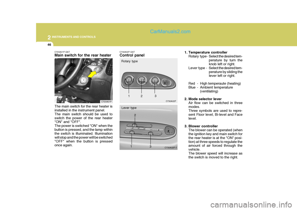
C720A01P-GAT Main switch for the rear heater The main switch for the rear heater is installed in the instrument panel. The main switch should be used toswitch the power of the rear heater "ON" and "OFF". The power is switched "ON" when thebutton is pressed, and the lamp within the switch is illuminated. Illumination will stop and the power will be switched"OFF" when the button is pressed once again. C720A01PC730A02P-GAT Control panel
Rotary type
Lever type C730A02P
C730A02P-1
1 2
3
12
3
1. Temperature controllerRotary type- Select the desired tem-
perature by turn the knob left or right.
Lever type - Select the desired tem-
perature by sliding thelever left or right.
Red - High temperaute (heating)
Blue - Ambi ent temperature
(ventilating)
2. Mode selector lever Air flow can be switched in three modes. Three symbols are used to repre- sent Floor level, Bi-level and Facelevel.
3. Blower controller The blower can be operated (when the ignition key and main switch for the rear heater is at the "ON" posi-tion) at three speeds to regulate the amount of air forced through the vehicle.The blower speed will increase as the switch is moved to the right.
Page 171 of 273

3
STARTING AND OPERATING
31LOCKING DIFFERENTIALADDITIONAL EQUIPMENT
D180M02P-GAT It is a good idea to carry a shovel or a short-handled spade in the vehicle during the winter so that you can clear away snow if you get stuck. A smallhand-brush for sweeping snow off the windscreen and rear window is also useful. D190A01HR-GAT (If Installed) A locking differential, if equipped, is for the rear wheel differential only. Thefeatures of this locking differential are described below: Just as with a conventional differential,the wheel on one side is allowed to turn at a different speed from the wheel on the other side when the vehicle iscornering. The difference between the locking differential and a conventional differential is that if the wheel on oneside of the vehicle loses traction, a greater amount of torque is applied to the rear wheel on the other side toimprove traction. NOTE: In a stationary position, the LD (Locking Differential) will operate when the difference of the revolu- tion speed between the rear rightwheel and the rear left wheel oc- curs.
CAUTION:(If installed)
White smoke may arise from thefuel fired heater outlet in the driver's front wheel housing during winterdriving. This is a normal condition. But, If a black (or gray) smoke is generated heavily, have the fuel firedheater checked by your Hyundai dealer. If the engine stops while the fuelfired heater is operating, whizzing noise may be heard from the lower of the battery in the engine com- partment. This is due to cleaning process forfuel fired heater and a normal op- eration. It will takes about 1- 3 minutes ac-cording to fuel quantity in the fuel fired heater fuel line.
!