2004 Hyundai H-1 (Grand Starex) air condition
[x] Cancel search: air conditionPage 11 of 273

1. Multi-function light switch
2. Seat warmer switch (If installed)
3. Horn/Driver's side airbag (If installed)
4. Rear heater switch (If installed)
5. Windshield wiper/Washer switch
6. Hazard warning switch
7. Front fog light switch (If installed)
8. 4WD Switch (If installed)
9. Rear fog light switch (If installed)
10. Rear window defroster switch
11. Passenger's side airbag (If installed)
12. Glove box13. Headlight leveling device switch (If installed)
14. ECT switch (Automatic transmission only)
15. Fuel-filler lid release lever
16. Hood release lever
17. Panel brightness control knob (Rheostat) (If installed)
18. Engine RPM adjustment knob (If installed)
19. Heater/Air conditioner control panel
20. Cigarette lighter
21. Ashtray
22. Drink holder
23. Audio system (If installed)
24. Digital clock (If installed)
CAUTION:
When installing the container of liquid air refresher inside a vehicle, do not place it near theinstrument cluster nor on the crash pad surface. If there is any leakage from the air refresher onto these areas (Instrument cluster, crash pad or air ventilator), it may damage these parts. If the liquid from air refresher does leak onto these areas, wash them with water immediately.
!
Page 13 of 273
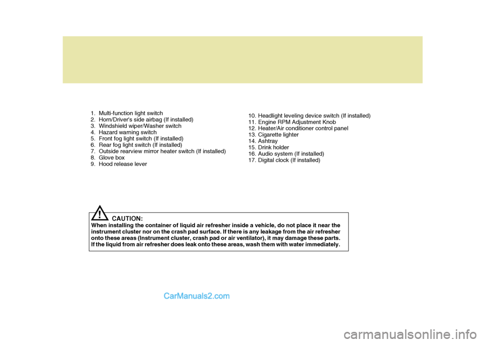
1. Multi-function light switch
2. Horn/Driver's side airbag (If installed)
3. Windshield wiper/Washer switch
4. Hazard warning switch
5. Front fog light switch (If installed)
6. Rear fog light switch (If installed)
7. Outside rearview mirror heater switch (If installed)
8. Glove box
9. Hood release lever10. Headlight leveling device switch (If installed)
11. Engine RPM Adjustment Knob
12. Heater/Air conditioner control panel
13. Cigarette lighter
14. Ashtray
15. Drink holder
16. Audio system (If installed)
17. Digital clock (If installed)
CAUTION:
When installing the container of liquid air refresher inside a vehicle, do not place it near theinstrument cluster nor on the crash pad surface. If there is any leakage from the air refresheronto these areas (Instrument cluster, crash pad or air ventilator), it may damage these parts. If the liquid from air refresher does leak onto these areas, wash them with water immediately.
!
Page 58 of 273

1BEFORE DRIVING YOUR VEHICLE
44
!
B230G01P-GAT Installation on Outboard Rear Seats To install a child restraint system in the outboard rear seats, extend the shoul- der/lap belt from its retractor. Install the child restraint system, buckle theseat belt and allow the seat belt to take up any slack. Make sure that the lap portion of the belt is tight around thechild restraint system and the shoulder portion of the belt is positioned so that it cannot interfere with the child's heador neck. After installation of the child restraint system, try to move it in all directions to be sure the child restraintsystem is securely installed. If you need to tighten the belt, pullmore webbing toward the retractor.When you unbuckle the seat belt and allow it to retract, the retractor will automatically revert back to its normalseated passenger emergency locking usage condition. NOTE:
o Before installing the child re-
straint system, read the instruc- tions supplied by the child re- straint system manufacturer.
o If the seat belt does not operate as described, have the systemchecked immediately by yourauthorized Hyundai dealer.
WARNING:
Do not install any child restraintsystem in the front passenger seat.Should an accident occur and cause the passenger side airbag to de- ploy, it could severely injure or killan infant or child seated in an infant or child seat. Therefore, install a child restraint system only in therear seat of your vehicle.
B230G01L-1
Use the center seat belt for the rearseat to secure the child restraint sys-tem as illustrated. After installation of the child restraint system, rock the child seat back and forth, and side toside to ensure that it is properly se- cured by the seat belt. If the child seat moves, readjust thelength of the seat belt. Always refer to the child restraint system manufacturer's recommendation be-fore installing the child restraint sys- tem in your vehicle.
Page 63 of 273

1
BEFORE DRIVING YOUR VEHICLE
49
!WARNING:
o When the SRS is activated, there may be a loud noise and fine dust will be released through the ve- hicle. These conditions are nor- mal and are not hazardous. How-ever, the fine dust generated dur- ing airbag deployment may cause skin irritation. Be sure to washyour hands and face thoroughly with lukewarm water and a mild soap after an accident in whichthe airbags were deployed. B240B05L
Passenger's Airbag
B240C01HP-GAT SRS Care The SRS is virtually maintenance-free and so there are no parts you cansafely service by yourself. The entire SRS system must be inspected by an authorized Hyundai dealer 10 yearsafter the date that the vehicle was manufactured. Any work on the SRS system, such as removing, installing, repairing, or any work on the steering wheel must beperformed by a qualified Hyundai tech- nician. Improper handling of the SRS system may result in serious personalinjury.
o The SRS can function only when
the ignition key is in the "ON" position. If the SRS SRI does not come on, or continuously re- mains on, after flashing for about6 seconds when the ignition key is turned to the "ON" position, or after the engine is started, orcomes on while driving, the SRS is not working properly. If this occurs, have your vehicle imme-diately inspected by your Hyundai dealer.
o Before you replace a fuse or dis-
connect a battery terminal, turnthe ignition key to the "LOCK" position or remove the ignitionkey. Never remove or replace the air bag related fuse(s) when the ignition key is in the "ON" posi-tion. Failure to heed this warning will cause the SRS SRI to illumi- nate.
Page 66 of 273

2
Instrument Cluster And Indicator Lights ....................... 2-2
Warning And Indicator Lights ....................................... 2-8
Instrument Cluster ......................................................2-12
Odometer/Trip odmeter .............................................. 2-14
Multim eter ................................................................... 2-16
Muti-funition Light Switch ........................................... 2-19
Windshield Wiper And Washer Switch .......................2-21
Headlamp Leveling Device System ........................... 2-23
Instrument Panel Light Control (Rheostat) ................ 2-24
Engine Rpm Adjustment Knob ................................... 2-24
Fog Lamp Switch ....................................................... 2-25
Front/Rear Window Defroster Switch ......................... 2-26
Interior Light ............................................................... 2-28
Sunroof ....................................................................... 2-30
Mirror .......................................................................... 2-34
Drink Holder ................................................................ 2-35
Ashtray ....................................................................... 2-36
Digital Clock ................................................................ 2-37
Horn ............................................................................ 2-37
Heating And Cooling Control ..................................... 2-38
Rear Heater And Air Conditioner ............................... 2-45
Overhead Air Conditioning ......................................... 2-47
Air Conditioner Filter ................................................... 2-47
Stereo Sound System ................................................ 2-49
Audio System ............................................................. 2-51
Antenna ...................................................................... 2-73
INSTRUMENTS AND CONTROLS
2
Page 89 of 273

2 INSTRUMENTS AND CONTROLS
24INSTRUMENT PANEL LIGHT CONTROL (RHEOSTAT)
C220A01P-GAT (Minibus/Van) (If installed)
HSRFL220
The instrument panel lights can be made brighter or dimmer by turning the instrument panel light control knob.
For loading conditions other than thoselisted, adjust the switch position sothat the beam level may be the nearest as the condition obtained according to the list.
MINIBUS2WD4WD 2WD
7/9
0 0 1 1 2 3 3 0
- - - -
1 6 0 0 0 0 1 2
7 0 0 1 1 2 3
LOADING
CONDITION
Driver only Driver + Frontpassenger Driver, front pas- senger + FarthestRear Seat Full Full passengers Full passengers +Maximum Permis- sible loading Driver+MaximumPermissible loading12 0
- - - -
1
LOADING CONDITION Driver onlyDriver + PermissibleRear axle load
TRUCK 0 1
VAN
ENGINE RPM ADJUSTMENT KNOB
C230A01P-GAT (Diesel) (If installed)
When the outside air temperature is very low, or when it is necessary to warm up the engine, then turn the knobclockwise to that point at which the engine runs smoothly, and then, once the warming up is completed, fully turnthe knob counterclockwise. CAUTION:
Never attempt to adjust the vehicleduring driving by using the control knob.
! HSRFL230
Page 106 of 273

2
INSTRUMENTS AND CONTROLS
41
B670B01A-AAT Fan Speed Control (Blower Control) This is used to turn the blower fan on or off and to select the fan speed.This blower fan speed, and therefore the volume of air delivered from the system, may be controlled manuallyby setting the blower control between the "1" and "4" positions.
Defrost-Level
Air is discharged through the wind-shield defroster nozzle and side venti- lator.If the "Defrost" mode is selected, the A/C will turn on automatically and "Fresh" mode will be activated to im-prove windshield defrosting. HSRFL674B670C01A-AAT AIR INTAKE CONTROL This is used to select fresh outside air or recirculating inside air.
Fresh Recirculation
With the mode selected, air enters the vehicle from outside and is heatedor cooled according to the other func- tions selected. With the mode selected, air fromwithin the passenger compartment is drawn through the heating system and heated or cooled according to the otherfunctions selected. NOTE: It should be noted that prolonged operation of the heating system in mode will give rise to misting
of the windshield and side win-dows and the air within the passen- ger compartment will become stale. In addition prolonged use of the airconditioning with the mode se- lected may result in the air within the passenger compartment becom-ing excessively dry.
Page 109 of 273

2 INSTRUMENTS AND CONTROLS
44AIR CONDITIONING SYSTEM
C680A01P-GAT (If installed) Cooling To use the air conditioner to cool inte- rior:
o Set the side vent control to "OFF",
to shut off outside air entry.
o Turn on the fan control switch.
o Turn on the air conditioner switch by pushing in on the switch. The air conditioner indicator light should come on at the same time.
o Set the air intake control to the "Fresh" position.
o Set the temperature control to the
"Cool" position. ("Cool" provides maximum cooling. The temperature may be moder- ated by moving the control toward"Warm".)
o Adjust the fan control to the desired
speed. For greater cooling, turn thefan control to one of the higher speeds or temporarily select the "Recirc" position on the air intakecontrol.
C680A01P C680A02P
Rotary and push button type
Lever type Rotary and push button type
Lever type
C690A01P-GAT Dehumidified heating
C690A01P
C690A02P