2004 Hyundai H-1 (Grand Starex) ignition
[x] Cancel search: ignitionPage 165 of 273

3
STARTING AND OPERATING
25
!
o Such objects may not be detected
by the system at very close range (approximately 300 mm).
WARNING:
If you don't hear an audible warn- ing sound or if the buzzer sounds intermittently when shifting the gearto "R" position, this indicate a mal- function in the back warning sys- tem. If this occurs, have your ve-hicle checked your Hyundai dealer as soon as possible. C400B01P-GAT Operation of the back warning system Operating condition: o The back warning system switch is
pushed with the ignition key "ON".
o Sensing distance in backing up is approximately 1200 mm (47 in.).
1st Warning
approx. 1200 mm
to 810 mm fromthe rear bumper Buzzer beeps intermittently.
SensingDistance Warning Sound 2nd Warning
approx. 800 mmto 410 mm fromthe rear bumperBuzzer soundsbeeps morefrequently. 3rd Warning
approx. 400 mm Buzzer sounds continously.
DRIVING FOR ECONOMY
C140A01A-GAT You can save fuel and get more kilo- meters from your car if you follow these suggestions:
o Drive smoothly. Accelerate at a moderate rate. Don't make "jack- rabbit" starts or full-throttle shiftsand maintain a steady cruising speed. Don't race between stop- lights. Try to adjust your speed tothat of the other traffic so you don't have to change speeds unneces- sarily. Avoid heavy traffic wheneverpossible. Always maintain a safe distance from other vehicles so you can avoidunnecessary braking. This also re- duces brake wear.
o Drive at a moderate speed. The faster you drive, the more fuel yourcar uses. Driving at a moderate speed, especially on the highway, isone of the most effective ways to reduce fuel consumption.
Page 185 of 273

4
CORROSION PREVENTION AND APPEARANCE CARE
13
4
IN CASE OF EMERGENCY
13TOWING
E070A01P-GAT Tow at the illustrated point. Using any part other than the designated towinghooks could result in damage to ve- hicle body. The regulations concern- ing towing may differ from country tocountry. Front (Minbus/Van)
Front (Truck) E070A01P
GY40240B It is recommended that you may obeythe regulations in your area. If yourvehicle is to be towed, pay careful attention to the following points.
1. Move the gearshift lever to neutral.
2. Be sure the towing speed is within
the legal limit.
3. On vehicles with steering lock sys-
tem, turn the ignition switch to "ACC" to unlock the steering wheel. If you will be using the turn signals whilebeing towed, turn the ignition switch to "ON" position.
4. To prevent the exhaust gas from
entering the towing vehicle, set theair selection lever on the heater control to the recirculation position. 5. Turn on the hazard warning lamps.
6. During towing, make sure that close
contact is maintained between the drivers of both vehicles, and that the vehicles travel at low speed.Avoid abrupt starting or stopping which might subject the vehicles to shock.
7. If the transmission is malfunction- ing or damaged, tow the vehiclewith the rear wheels raised off theground.
8. If the vehicle is equipped with a
brake booster system, the brakeboosting power will be lost and greater force will be required to depress the brake pedal.
9. If the vehicle is equipped with a power steering system, greaterforce will be required to operate thesteering wheel.
NOTE: Your vehicle should only be used to tow another vehicle if the weightof the other vehicle is less than that of your vehicle.
JFS920-1
Rear (Minbus, Van)
Tie-down hook
Page 192 of 273

44IN CASE OF EMERGENCY
20IF THE ENGINE WILL NOT START
!WARNING:
o Do not smoke or have any other open flame near the vehicle while bleeding the fuel system.
o Be sure to carefully wipe away
any water drained out in thismanner, because the fuel mixed in the water might be ignited and result in a fire.
NOTE: It is recommended that water accu- mulated in the fuel filter should be removed by an authorized Hyundaidealer.
!
D010A01A-AAT
WARNING:
If the engine will not start, do not push or pull the car to start it. This could result in a collision or causeother damage. In addition, push or pull starting may cause the cata- lytic converter to be overloaded andcreate a fire hazard.
2. Operate the hand pump slowly 6 or 7 times in order to force the waterout through the drain plug.
3. Tighten the drain plug when water no longer comes out.
4. Loosen the air plug and bleed the air. (Refer to "Bleeding the fuel sys- tem".)
5. Check to be sure that the warning lamp illuminates when the ignitionkey is turned to "ON", and that itgoes off when the engine is started. If in doubt, consult your nearest authorized HYUNDAI dealer. Pump
GS40320A
Page 193 of 273

4
CORROSION PREVENTION AND APPEARANCE CARE
21
4
IN CASE OF EMERGENCY
21
D010B02A-AAT If Engine Doesn't Turn Over or Turns Over Slowly
1. If your car has an automatic
transaxle, be sure the gear selector lever is in "N" or "P" and the emer-gency brake is set.
2. Check the battery connections to be
sure they are clean and tight.
3. Turn on the interior light. If the light dims or goes out when you operatethe starter, the battery is discharged.
4. Check the starter connections to be sure they are securely tightened.
5. Do not push or pull the vehicle to start it. See instructions for "Jump Starting". D010B02P
D010D01A-AAT If the Engine Stalls While Driving
1. Reduce your speed gradually, keep-ing a straight line. Move cautiously off the road to a safe place.
2. Turn on your emergency flashers.
3. Try to start the engine again. If your
vehicle will not start, contact a Hyundai dealer or seek other quali- fied assistance.
If Engine Turns Over Normally but Does Not Start 1. Check fuel level. 2. With the key in the "OFF" position,
check all connectors at ignition coils and spark plugs(For Gasoline En- gine) or check all connectors atglow plug and glow plug relay(For Diesel Engine). Reconnect any that may be disconnected or loose.
3. Check fuel line in the engine room. 4. If engine still refuses to start, call a
Hyundai dealer or seek other quali- fied assistance.
JUMP STARTING
!
HA1FL4001
WARNING:
The gas produced by the battery during the jump-start operation is highly explosive. If these instruc-tions are not followed exactly, seri- ous personal injury and damage to the vehicle may occur! If you arenot sure how to follow this proce- dure, seek qualified assistance. Automobile batteries contain sul-furic acid. This is poisonous and highly corrosive. When jump start- ing, wear protective glasses and becareful not to get acid on yourself, your clothing or on the car. E110A02P-GAT
Discharged battery
Booster battery
Page 197 of 273

4
CORROSION PREVENTION AND APPEARANCE CARE
25
4
IN CASE OF EMERGENCY
25
If you suspect a blown fuse, follow this procedure:
1. Turn off the ignition and all other
switches.
2. Open the fuse box and examine each fuse. Remove each fuse by pulling it toward you (a small "fusepuller" tool is contained in the fuse box to simplify this operation).
3. Be sure to check all other fuses even if you find one that appears tohave burned out.
HSR40224. Replace the blown fuse by pressing
a new fuse of the same rating into place. The fuse should be a snug fit. If it is not, have the fuse clip repaired or replaced by a Hyundai dealer. Ifyou do not have a spare fuse, you may be able to borrow a fuse of the same or lower rating from an acces-sory you can temporarily get along without (the radio or cigarette light- er, for example). Always rememberto replace the borrowed fuse.
G200B02A
Good
Burned out
!
CAUTION:
A burned-out fuse indicates that there is a problem in the electrical circuit. If you replace a fuse and it blows as soon as the accessory isturned on, the problem is serious and should be referred to a Hyun- dai dealer for diagnosis and repair.Never replace a fuse with anything except a fuse with the same or a lower amperage rating. A highercapacity fuse could cause damage and create a fire hazard. NOTE: See page 4-37 for the fuse panel descriptions.
Page 209 of 273

4
CORROSION PREVENTION AND APPEARANCE CARE
37
4
IN CASE OF EMERGENCY
37FUSE PANEL DESCRIPTION
G200B01P-GAT MINIBUS/VAN Engine Compartment (Diesel Engine)
G200A01P
NOTE: Not all fuse panel descriptions in this manual may be applicable to your vehicle. It is accurate at the time of printing. When you inspect the fuse box on your vehicle, refer to the fuse box label. AMPE-
RAGES
120A80A 30A30A30A40A30A 40A30A 30A 40A 50A
15A/20A
10A30A10A 10A 10A15A 10A 10A15A CIRCUIT PROTECTED
Generator
Glow relay, Glow control module (D4BB) ABS control module
Blower relay
Rear blower relay Fuse 16, 25, 26
Condenser fan main relay, Condenser fan relay (LOW)
Ignition switch, Generator, Start relay, COMP. Fuse, I/C FAN Fuse, ECU Fuse. ABS control module
Power window relay, Siren relay
Tail lamp relay, Head lamp relay
Front fog lamp relay, Horn relay, Power connector
Inter cooler fan relay, Air temperature switch/Windshield glass defogger
A/C compressor relay
Main power relay (D4CB), Engine control relay, Fuel pump relay(Gasoline)
Illuminations, Left rear combination lamp, Left license lamp
Illuminations, Right rear combination lamp, Right license lamp
Left/Right horn
Front fog lamp switch, Left /Right front fog lampLeft head lamp
Right head lamp, Instrument cluster
Hazard relay, Fuse 23, 24
ALT
GLOW ABS
FR HTR
RR HTR DEF.
C/FAN
IGN
ABS P/W
TAIL
BATT
I/C FAN/FR HTD COMP.
ECU
T/LP(LH) T/LP(LH) HORN
FOG
H/LP(LH)
H/LP(RH)
FUSIBLE
LINK
FUSE
DESCRIPTION
POWER CONNECTOR
Page 210 of 273

44IN CASE OF EMERGENCY
38
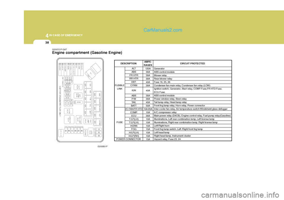
G200C01P-GAT Engine compartment (Gasoline Engine)
G200B01P AMPE-
RAGES
120A30A 30A30A40A30A 40A30A 30A 40A 50A
15A/20A
10A30A10A 10A 10A15A 10A 10A15A CIRCUIT PROTECTED
GeneratorABS control module
Blower relay
Rear blower relayFuse 16, 25, 26
Condenser fan main relay, Condenser fan relay (LOW)
Ignition switch, Generator, Start relay, COMP. Fuse,FR HTD Fuse,ECU Fuse. ABS control module
Power window relay, Siren relay
Tail lamp relay, Head lamp relay
Front fog lamp relay, Hor n relay, Power connector
Inter cooler fan relay, Air temperature switch/Windshield glass defogger
A/C compressor relay
Main power relay (D4CB), Engine control relay, Fuel pump relay(Gasoline)
Illuminations, Left rear combination lamp, Left license lamp
Illuminations, Right rear combination lamp, Right license lamp
Left/Right horn
Front fog lamp switch, Left /Right front fog lamp Left head lamp
Right head lamp, Instrument cluster
Hazard relay, Fuse 23, 24
ALT
ABS
FR HTR
RR HTR
DEF.
C/FAN
IGN
ABS P/W
TAIL
BATT
I/C FAN/FR HTD
COMP.ECU
T/LP(LH) T/LP(LH) HORNFOG
H/LP(LH)
H/LP(RH)
FUSIBLE
LINK
FUSE
DESCRIPTION
POWER CONNECTOR
Page 212 of 273

44IN CASE OF EMERGENCY
40
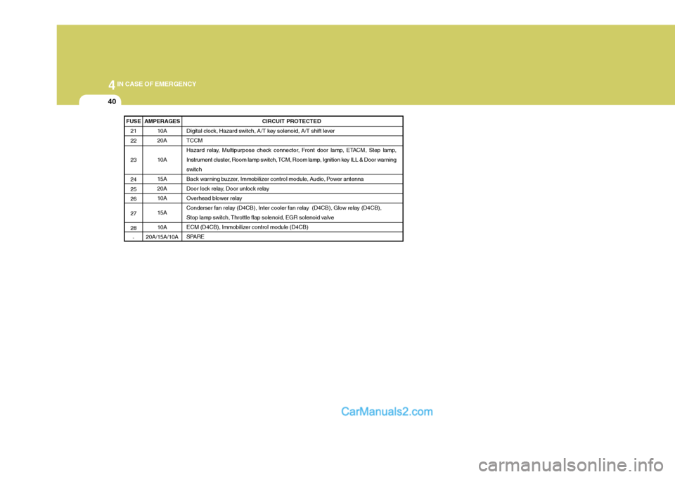
FUSE21 22 23 24 2526 27 28- CIRCUIT PROTECTED
Digital clock, Hazard switch, A/T key solenoid, A/T shift lever TCCM
Hazard relay, Multipurpose check connector, Front door lamp, ETACM, Step lamp,
Instrument cluster, Room lamp switch, TCM, Room lamp, Ignition key ILL & Door warning
switch
Back warning buzzer, Immobilizer control module, Audio, Power antenna
Door lock relay, Door unlock relay
Overhead blower relay
Conderser fan relay (D4CB), Inter cooler fan relay (D4CB), Glow relay (D4CB),
Stop lamp switch, Throttle flap solenoid, EGR solenoid valve
ECM (D4CB), Immobilizer control module (D4CB)
SPARE
AMPERAGES 10A 20A 10A15A 20A10A 15A10A
20A/15A/10A