2004 Hyundai Coupe cooling
[x] Cancel search: coolingPage 265 of 389
1
FEATURES OF YOUR HYUNDAI
85
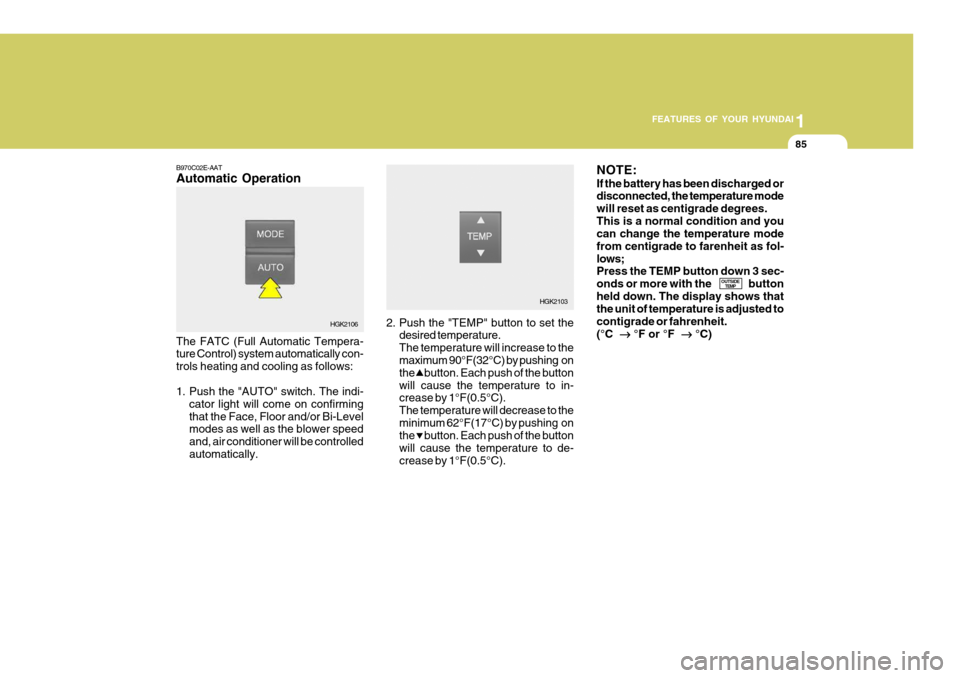
B970C02E-AAT Automatic Operation The FATC (Full Automatic Tempera- ture Control) system automatically con- trols heating and cooling as follows:
1. Push the "AUTO" switch. The indi-
cator light will come on confirming that the Face, Floor and/or Bi-Level modes as well as the blower speed and, air conditioner will be controlledautomatically. 2. Push the "TEMP" button to set the
desired temperature.The temperature will increase to the maximum 90°F(32°C) by pushing on the button. Each push of the buttonwill cause the temperature to in- crease by 1°F(0.5°C). The temperature will decrease to theminimum 62°F(17°C) by pushing on the button. Each push of the button will cause the temperature to de-crease by 1°F(0.5°C).NOTE: If the battery has been discharged or disconnected, the temperature mode will reset as centigrade degrees.This is a normal condition and you can change the temperature mode from centigrade to farenheit as fol-lows; Press the TEMP button down 3 sec- onds or more with the buttonheld down. The display shows that the unit of temperature is adjusted to contigrade or fahrenheit.(°C ��
��
� °F or °F
��
��
� °C)
OUTSIDE
TEMP
HGK2106 HGK2103
Page 266 of 389

1FEATURES OF YOUR HYUNDAI
86
NOTE: Never place anything over the sen- sor which is located on the instru-ment panel to ensure better control of the heating and cooling system. Photo sensor
B995A01Y-GAT AMBIENT SWITCH Pressing the button displays the amb-ient temperature on the dis-play.
OUTSIDE
TEMP B980A01Y-AAT MANUAL OPERATION The heating and cooling system can be controlled manually as well by pushingbuttons other than the "AUTO" button. In this state, the system sequentially works according to the order of buttonsselected. The function of the buttons which are not selected will be controlled automati-cally. Press the "AUTO" button in order to convert to automatic control of the sys-tem.
HGK2109
HGK2076-E
Page 269 of 389
1
FEATURES OF YOUR HYUNDAI
89
!
o When the ignition switch is turned
"ON" the air intake control will change to "Fresh" mode (regard- less of switch position). It is nor- mal operation. The air intake con-trol is operated in "AUTO" mode when turning the ignition to the ON position if the "AUTO" modewas used before shutting off the engine.
CAUTION:
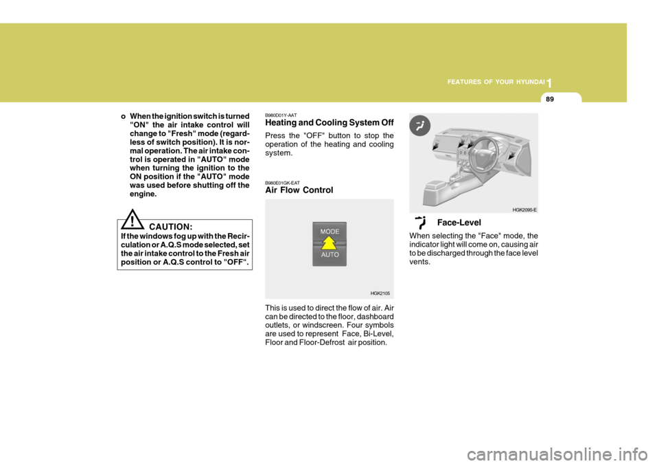
If the windows fog up with the Recir- culation or A.Q.S mode selected, setthe air intake control to the Fresh air position or A.Q.S control to "OFF". B980D01Y-AAT Heating and Cooling System Off Press the "OFF" button to stop the operation of the heating and coolingsystem. B980E01GK-EAT Air Flow Control This is used to direct the flow of air. Air can be directed to the floor, dashboard outlets, or windscreen. Four symbols are used to represent Face, Bi-Level,Floor and Floor-Defrost air position.
Face-Level
When selecting the "Face" mode, the indicator light will come on, causing air to be discharged through the face levelvents.
HGK2105 HGK2095-E
Page 292 of 389
2DRIVING YOUR HYUNDAI
16
SC170A1-E The onset of winter conditions subject motor vehicles to greater operating demands. Therefore, the following suggestions will assist in maintainingpeak performance and reliability dur- ing these periods:WINTER MOTORING
ZC170B1-E Electrical System Winter conditions impose severe de- mands upon vehicle electrical systems,particularly the charging circuit. The battery condition and performance along with the alternator performanceand drive belt condition should be checked prior to the onset of winter.SC160A1-F Avoid braking or gear changing in cor- ners, especially when roads are wet. Ideally, corners should always be taken under gentle acceleration. If you followthese suggestions, tire wear will be held to a minimum.SMOOTH CORNERING
ZC170C1-E Anti-freeze/Corrosion inhibitor The cooling system must always con- tain an Ethylene-Glycol based anti- freeze solution. The system is filledduring manufacture with solution of the correct strength which should be checked before the onset of winter andadjusted or changed as required. NOTE: The anti-freeze solution contains a corrosion inhibitor to prevent deg-radation of the aluminum castings contained within the engine. There- fore, never, drain the system andrefill with water only.
Page 302 of 389

3 IN CASE OF EMERGENCY
4
7. Swithc "ON" the main beam
headlamps before carefully remov- ing the jumper cables have been removed, switch "OFF" the main beam geadlamps. SD040A2-E If the temperature gauge indicates overheating:
1. Pull off the road and stop as soon as
it is safe to do so.
2. Place the gear selector lever in "P"
(automatic), or neutral (manual transaxle) and set the parking brake. If the air conditioning is on, turn it off.
3. If coolant is running out under the car or steam is coming out fromunder the bonnet stop the engine. Do not open the bonnet until thecoolant has stopped running or the steaming has stopped. If there is no visible loss of coolant and no steam,leave the engine running and check to be sure the engine cooling fan is operating.If the fan is not running, turn the engine off.
4. Check to see if the water pump drive belt is missing. If it is not missing,check to see that it is tight. If the drive belt seems to be satisfac-tory,check for coolant leaking from the radiator, hoses or under the car. (If the air conditioning had been in use,it is normal for cold water to be draining from it).
IF THE ENGINE OVERHEATS
1. Ensure that the booster battery is 12 volt type. If the booster battery is installed in another vehicle, ensure that the two vehicles are not touch- ing.
2. Turn off all unnecessary electrical equipment in both vehicles.
3. Ensure that the engine of the ve- hicle providing the jump start is run- ning prior to connection of the jump cables.
4. Connect the red jump cable to the positive (+) terminal of the boosterbattery and the other end to thepositive (+) terminal of the dis- charged battery.
5. Attach the black jump cable to the negative (-) terminal of thebooster battery, and the other end to a ground point within the enginecompartment of the vehicle with the flat battery. Do not connect to the negative battery terminal of the flatbattery since sparks may be gener- ated with the subsequent risk of explosion.
6. Raise the booster vehicle engine speed to 2,000 r.p.m. and start theengine of the vehicle with the flatbattery. CAUTION:
If the jump cable is incorrectly in-stalled, damage to the vehicle elec-trical system may occur, in particu- lar the electronic components such as the Fuel Injection system com- puter and the Automatic Transaxle computer. The battery must neverbe disconnected whilst the engine is running.
!
Page 303 of 389
3
IN CASE OF EMERGENCY
5
!
!WARNING:
Whilst the engine is running, keep hands and clothing away from mov- ing parts such as the fan and drive belts to prevent injury.
5. If the water pump drive belt is bro- ken or coolant is leaking out, stop the engine immediately and call the nearest Hyundai dealer for assis-tance.
WARNING:
Do not remove the radiator cap when the engine is hot since steam and boiling water may be ejected fromthe radiator resulting in burns or scalding.
!
6. If the cause of the overheating can- not be found, wait until the engine temperature has returned to nor- mal. Then, if coolant has been lost, carefully add coolant to the reser-voir (page 6-11) to bring the fluid level in the reservoir up to the base of the radiator fill opening. Fill thecoolant expansion tank to the half- way mark.
7. Proceed with caution until it is es- tablished that the engine is operat-ing normally. If the engine over- heats repeatedly, the advice of aHyundai dealer should be sought.
CAUTION:
Serious loss of coolant indicatesthere is a leak in the cooling systemand this should be checked as soon as possible by a Hyundai dealer.D040A01GK-EAT TEMPORARY SPARE TYRE The following instructions for the tem- porary spare tyre should be observed:
1. Check inflation pressure as soon as practical after installing the spare tyre, and adjust to the specified pressure. The tyre pressure should be periodically checked and main-tained at the specified pressure while the tyre is stored.
2. The spare tyre should only be used temporarily and should be returnedto the luggage compartment as soon as the original tyre can be repairedor replaced.
SPARE TYRE
Tyre Size
Inflation Pressure T125/70 R16
420 kPa (60 psi)
Spare Tyre Pressure
3. Continuous use at speeds of over 50 mph (80 km/h) is not recom- mended.
4. As the temporary spare tyre is spe-
cifically designed for your car, itshould not be used on any other vehicle.
Page 321 of 389
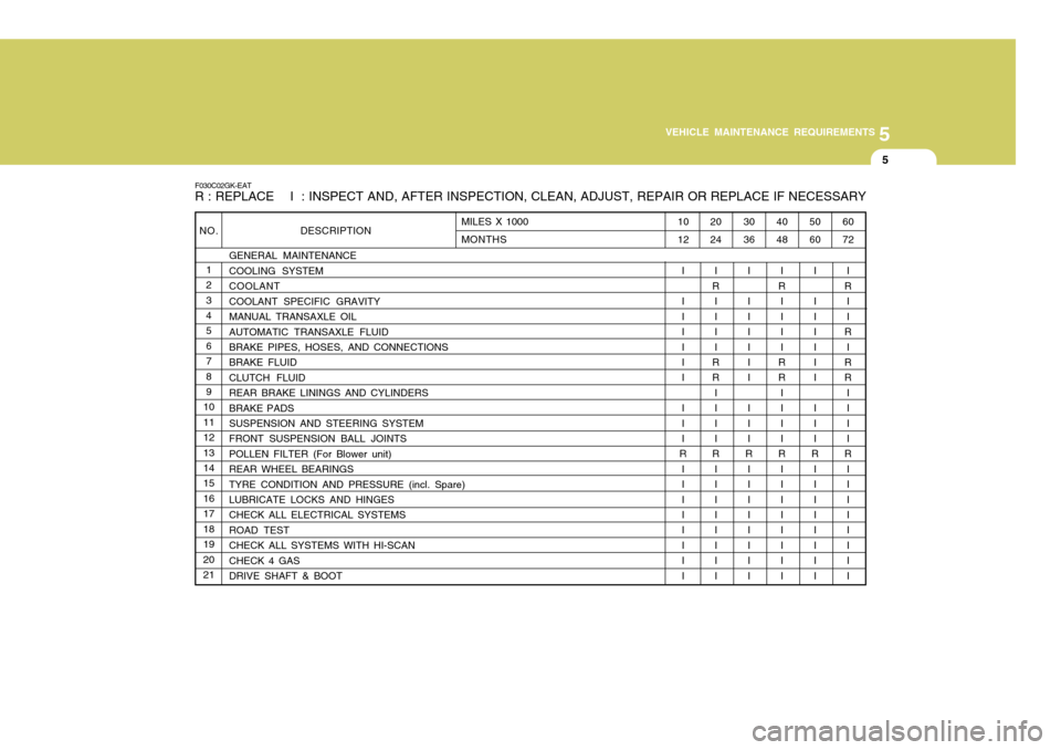
5
VEHICLE MAINTENANCE REQUIREMENTS
5
NO. 1 23 4 5678 9
10 11121314 15 1617181920 21 DESCRIPTION
GENERAL MAINTENANCE COOLING SYSTEMCOOLANTCOOLANT SPECIFIC GRAVITYMANUAL TRANSAXLE OILAUTOMATIC TRANSAXLE FLUID BRAKE PIPES, HOSES, AND CONNECTIONS BRAKE FLUIDCLUTCH FLUIDREAR BRAKE LININGS AND CYLINDERSBRAKE PADS SUSPENSION AND STEERING SYSTEM FRONT SUSPENSION BALL JOINTSPOLLEN FILTER (For Blower unit)REAR WHEEL BEARINGSTYRE CONDITION AND PRESSURE (incl. Spare)LUBRICATE LOCKS AND HINGES CHECK ALL ELECTRICAL SYSTEMS ROAD TESTCHECK ALL SYSTEMS WITH HI-SCANCHECK 4 GASDRIVE SHAFT & BOOT
F030C02GK-EAT R : REPLACE I : INSPECT AND, AFTER INSPECTION, CLEAN, ADJUST, REPAIR OR REPLACE IF NECESSARY
60 72
I
R I I
R
I
RR
III I
R
I III I III
50 60
I I III I I I I I
R I III I III
40 48
I
R
I III
RR
III I
R I III I III
30 36
I I III I I I I I
R I III I III
20 24
I
R I III
RR
III I
R I III I III
10 12
I I III I I I I I
R I III I III
MILES X 1000 MONTHS
Page 324 of 389

5VEHICLE MAINTENANCE REQUIREMENTS
8
6ZF060F1-A
o Vacuum, crankcaseventilation hoses
Inspect the surface of hoses for evi- dence of heat and/or mechanical dam- age. Hard and brittle rubber, cracking, tears, cuts, abrasions, and excessiveswelling indicate deterioration. Particu- lar attention should be paid to examin- ing those hose surfaces nearest tohigh heat sources, such as the ex- haust manifold. Inspect the hose routing to assure that the hoses do not come in contact with any heat source, sharp edges or mov- ing component which might cause heatdamage or mechanical wear. Inspect all hose connections, such as clamps and couplings, to make sure they aresecure, and that no leaks are present. Hoses should be replaced immedi- ately if there is any evidence of dete-rioration or damage. 6ZF060H1-A
o Air cleaner filter
A Genuine Hyundai air cleaner filter is
recommended when the filter is re- placed.
6ZF060J1-A
o Spark plugs
Make sure to install new spark plugs
of the correct heat range.
F060N02E-EAT
o Valve Clearance
Inspect excessive valve noise and/or
engine vibration and adjust if neces- sary. A qualified technician should perform the operation. 6ZF070B1-A
o Cooling system
Check the cooling system part, such
as radiator, coolant reservoir, hosesand connections for leakage and dam- age. Replace any damaged parts.
6ZF070C1-A
o Coolant
The coolant should be changed at
the intervals specified in the mainte-nance schedule.
6ZF070D1-A
o Manual transaxle oil
Inspect the manual transaxle oil ac-
cording to the maintenance schedule. NOTE:
If the oil level is low, check for
possible leaks before adding oil. Do not overfill.