2004 Hyundai Coupe steering wheel
[x] Cancel search: steering wheelPage 211 of 389
1
CONTROLS AND EQUIPMENT
31
!
tection than that offered by the seat belt system alone, in case of a frontalimpact of sufficient severity. NOTE: Be sure to read information about the SRS on the labels provided onthe front side of the sun visor and in the glove box.
WARNING:
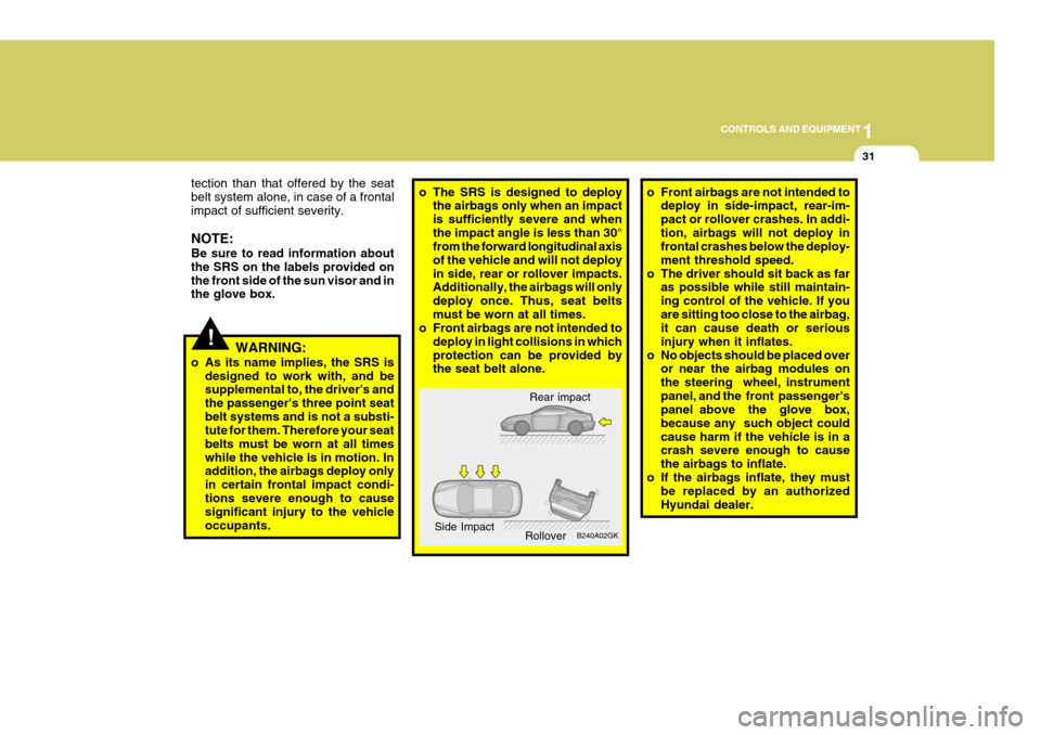
o As its name implies, the SRS is designed to work with, and besupplemental to, the driver's and the passenger's three point seatbelt systems and is not a substi- tute for them. Therefore your seat belts must be worn at all timeswhile the vehicle is in motion. In addition, the airbags deploy only in certain frontal impact condi-tions severe enough to cause significant injury to the vehicle occupants.o The SRS is designed to deploy the airbags only when an impact is sufficiently severe and whenthe impact angle is less than 30° from the forward longitudinal axis of the vehicle and will not deployin side, rear or rollover impacts. Additionally, the airbags will only deploy once. Thus, seat beltsmust be worn at all times.
o Front airbags are not intended to
deploy in light collisions in whichprotection can be provided by the seat belt alone. o Front airbags are not intended to
deploy in side-impact, rear-im- pact or rollover crashes. In addi-tion, airbags will not deploy in frontal crashes below the deploy- ment threshold speed.
o The driver should sit back as far as possible while still maintain-ing control of the vehicle. If youare sitting too close to the airbag, it can cause death or serious injury when it inflates.
o No objects should be placed over or near the airbag modules onthe steering wheel, instrumentpanel, and the front passenger's panel above the glove box, because any such object couldcause harm if the vehicle is in a crash severe enough to cause the airbags to inflate.
o If the airbags inflate, they must be replaced by an authorizedHyundai dealer.
Rear impact
B240A02GK
Side Impact
Rollover
Page 213 of 389

1
CONTROLS AND EQUIPMENT
33
The SRS service reminder indicator (SRI) on the instrument panel will comeon for about 6 seconds after the igni- tion key is turned to the "ON" position or after the engine is started, afterwhich the SRI should go out. The airbag modules are located both in the centre of the steering wheel and in the front passenger's panel above the glove box. When the SRSCM de-tects a considerable impact to the front of the vehicle, it will automatically de- ploy the airbags. B240B02L-R Passenger's Airbag
Upon deployment, tear seams moldeddirectly into the pad covers will sepa-rate under pressure from the expan- sion of the airbags. Further opening of the covers then allows full inflation ofthe airbags. A fully inflated airbag in combination with a properly worn seat belt slows the driver's or the passenger's forward motion, thus reducing the risk of headand chest injury. After complete inflation, the airbag immediately starts deflating, enabling the driver to maintain forward visibility. B240B03L-R
B240B01GK-E
!
CAUTION:
Do not install or place any accesso- ries (drink holder, cassette holder, sticker, etc) on the front passenger'spanel above the glove box in the vehicle with passenger's side air bag. Such objects may becomedangerous projectiles and cause injury if the passenger's side air bag inflates.
Page 215 of 389

1
CONTROLS AND EQUIPMENT
35
B990B04Y-EAT Side Impact Airbag (Not all models)
B990B02Y-R
Your Hyundai is equipped with a side impact airbag in each front seat. Thepurpose of the airbag is to provide the vehicle's driver and/or the front pas- senger with additional protection thanthat offered by the seatbelt alone. The side impact airbags are designed to deploy only during certain side-impactcollisions, depending on the crash se- verity, angle, speed and point of im- pact. The side impact air bags are notdesigned to deploy in all side impact situations.
!WARNING:
o The side impact airbag is supple- mental to the driver's and the passenger's seat belt systems and is not a substitute for them. Therefore your seat belts mustbe worn at all times whilst the vehicle is in motion. The airbags deploy only in certain side im-pact conditions severe enough to cause significant injury to the vehicle occupants.
o For best protection from the side
impact airbag system and toavoid being injured by the de- ploying side impact airbag, both front seat occupants should sitin an upright position with the seat belt properly fastened. The driver's hands should be placedon the steering wheel at the 9:00 and 3:00 o'clock positions. The passenger's arms and handsshould be placed on their laps. o Do not use any accessory seat
covers.
o Use of seat covers could prevent
or reduce the effectiveness of the system.
o Do not install any accessories on
the side or near the side impactairbag.
o Do not use excessive force on the side of the seat.
o Do not place any objects over the
airbag or between the airbag and yourself.
o Do not place any objects (an
umbrella, bag, etc.) between the front door and the front seat. Such objects may become dan-gerous projectiles and cause in- jury if the supplemental side im- pact air bag inflates.
o To prevent unexpected deploy- ment of the side impact air bagthat may result in personalinjury,avoid impact to the side airbag sensor when the ignition key is on.
Page 216 of 389
1CONTROLS AND EQUIPMENT
36
B240C01HP
!WARNING:
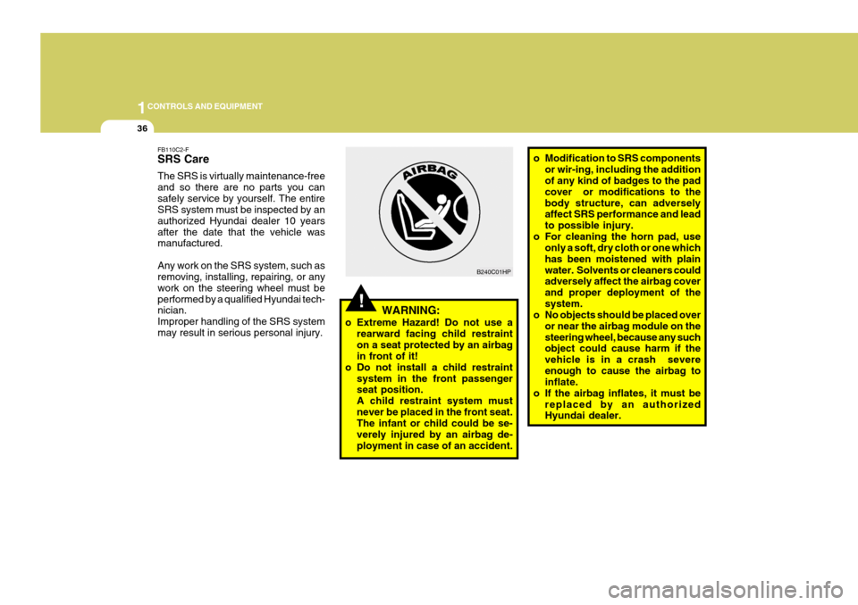
o Extreme Hazard! Do not use a rearward facing child restraint on a seat protected by an airbag in front of it!
o Do not install a child restraint system in the front passengerseat position. A child restraint system mustnever be placed in the front seat. The infant or child could be se- verely injured by an airbag de-ployment in case of an accident. o Modification to SRS components
or wir-ing, including the addition of any kind of badges to the pad cover or modifications to thebody structure, can adversely affect SRS performance and lead to possible injury.
o For cleaning the horn pad, use only a soft, dry cloth or one whichhas been moistened with plainwater. Solvents or cleaners could adversely affect the airbag cover and proper deployment of thesystem.
o No objects should be placed over
or near the airbag module on thesteering wheel, because any such object could cause harm if the vehicle is in a crash severeenough to cause the airbag to inflate.
o If the airbag inflates, it must be
replaced by an authorizedHyundai dealer.
FB110C2-F SRS Care The SRS is virtually maintenance-free and so there are no parts you cansafely service by yourself. The entire SRS system must be inspected by an authorized Hyundai dealer 10 yearsafter the date that the vehicle was manufactured. Any work on the SRS system, such as removing, installing, repairing, or any work on the steering wheel must beperformed by a qualified Hyundai tech- nician. Improper handling of the SRS systemmay result in serious personal injury.
Page 230 of 389
1CONTROLS AND EQUIPMENT
50MULTI FUNCTION SWITCH
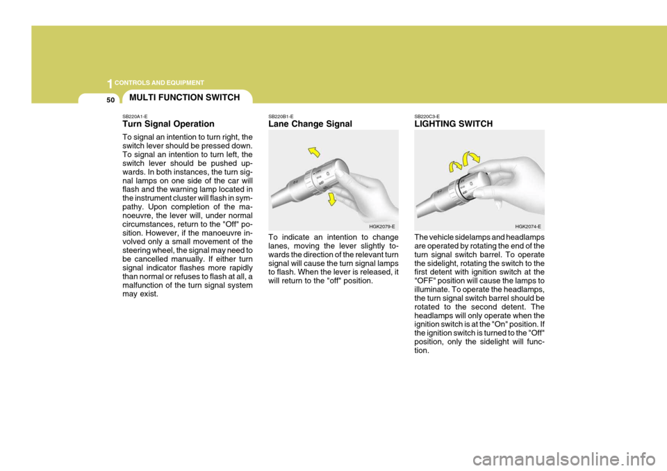
SB220A1-E Turn Signal Operation To signal an intention to turn right, the switch lever should be pressed down.To signal an intention to turn left, the switch lever should be pushed up- wards. In both instances, the turn sig-nal lamps on one side of the car will flash and the warning lamp located in the instrument cluster will flash in sym-pathy. Upon completion of the ma- noeuvre, the lever will, under normal circumstances, return to the "Off" po-sition. However, if the manoeuvre in- volved only a small movement of the steering wheel, the signal may need tobe cancelled manually. If either turn signal indicator flashes more rapidly than normal or refuses to flash at all, amalfunction of the turn signal system may exist. SB220B1-E Lane Change Signal To indicate an intention to change lanes, moving the lever slightly to- wards the direction of the relevant turnsignal will cause the turn signal lamps to flash. When the lever is released, it will return to the "off" position.
SB220C3-E LIGHTING SWITCH The vehicle sidelamps and headlamps are operated by rotating the end of the turn signal switch barrel. To operatethe sidelight, rotating the switch to the first detent with ignition switch at the "OFF" position will cause the lamps toilluminate. To operate the headlamps, the turn signal switch barrel should be rotated to the second detent. Theheadlamps will only operate when the ignition switch is at the "On" position. If the ignition switch is turned to the "Off"position, only the sidelight will func- tion.
HGK2079-E
HGK2074-E
Page 232 of 389
1CONTROLS AND EQUIPMENT
52
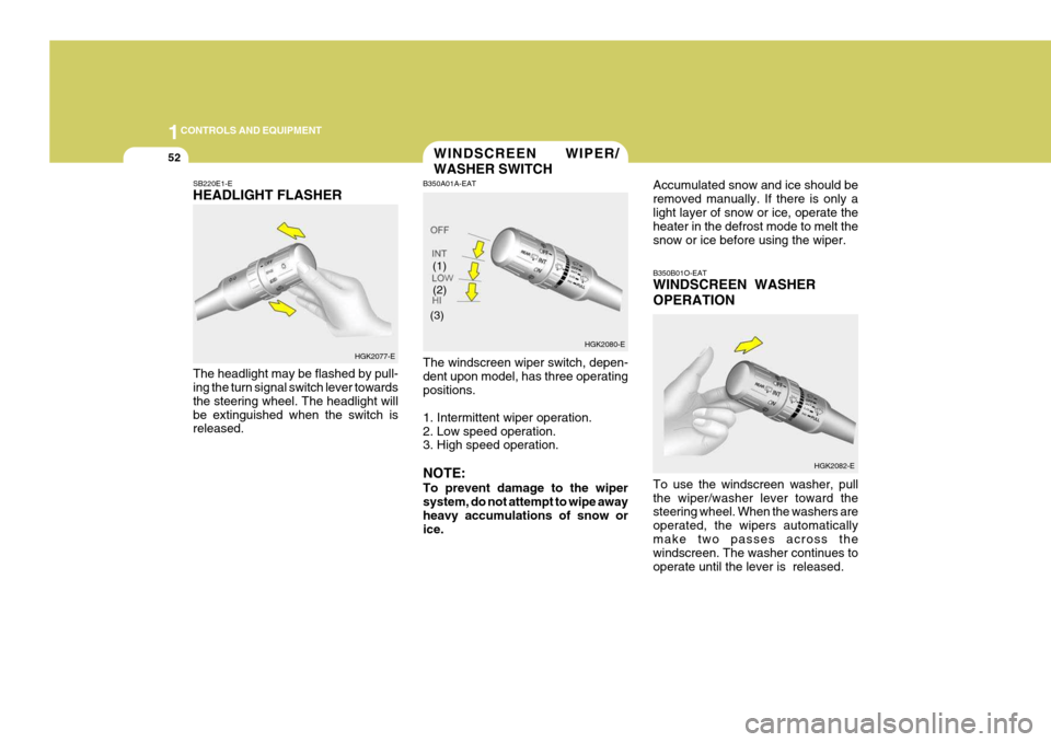
(2) B350B01O-EAT WINDSCREEN WASHER OPERATION To use the windscreen washer, pull the wiper/washer lever toward the steering wheel. When the washers are operated, the wipers automaticallymake two passes across the windscreen. The washer continues to operate until the lever is released.HGK2082-E
WINDSCREEN WIPER/ WASHER SWITCH
SB220E1-E HEADLIGHT FLASHER The headlight may be flashed by pull- ing the turn signal switch lever towards the steering wheel. The headlight willbe extinguished when the switch is released. B350A01A-EAT The windscreen wiper switch, depen- dent upon model, has three operatingpositions. 1. Intermittent wiper operation. 2. Low speed operation. 3. High speed operation. NOTE: To prevent damage to the wiper system, do not attempt to wipe away heavy accumulations of snow orice. Accumulated snow and ice should beremoved manually. If there is only alight layer of snow or ice, operate the heater in the defrost mode to melt the snow or ice before using the wiper.
HGK2077-E HGK2080-E
(1)
(3)
Page 249 of 389
1
CONTROLS AND EQUIPMENT
69
!
NOTE: The Supplemental Restraint Sys- tem (SRS) label containing useful information can be found on thefront of each sun visor.
WARNING:
Do not place the sunvisor in such a manner that it obscures visibility of the roadway, traffic or the objects.
!
STEERING WHEEL TILT LE- VER
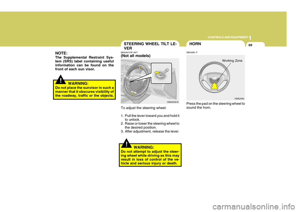
B600A01HP-AAT (Not all models) To adjust the steering wheel:
1. Pull the lever toward you and hold it
to unlock.
2. Raise or lower the steering wheel to
the desired position.
3. After adjustment, release the lever.
WARNING:
Do not attempt to adjust the steer- ing wheel while driving as this mayresult in loss of control of the ve- hicle and serious injury or death. HGK2049-E
HGK2050
HORN
SB530B1-F Press the pad on the steering wheel to sound the horn.
Working Zone
Page 251 of 389
1
CONTROLS AND EQUIPMENT
71
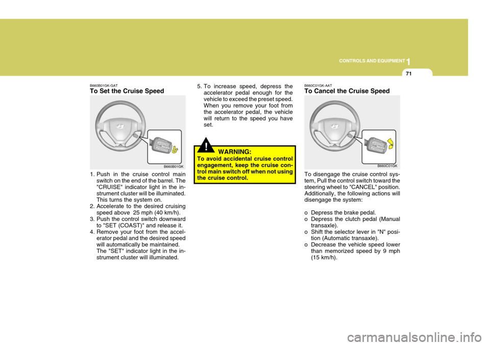
B660B01GK-GAT To Set the Cruise Speed
1. Push in the cruise control main
switch on the end of the barrel. The "CRUISE" indicator light in the in-strument cluster will be illuminated. This turns the system on.
2. Accelerate to the desired cruising speed above 25 mph (40 km/h).
3. Push the control switch downward
to "SET (COAST)" and release it.
4. Remove your foot from the accel- erator pedal and the desired speed will automatically be maintained.The "SET" indicator light in the in- strument cluster will illuminated. B660B01GK
!
5. To increase speed, depress the
accelerator pedal enough for the vehicle to exceed the preset speed. When you remove your foot from the accelerator pedal, the vehiclewill return to the speed you have set.
WARNING:
To avoid accidental cruise controlengagement, keep the cruise con- trol main switch off when not using the cruise control.B660C01GK-AAT To Cancel the Cruise Speed To disengage the cruise control sys- tem, Pull the control switch toward the steering wheel to "CANCEL" position.Additionally, the following actions will disengage the system:
o Depress the brake pedal.
o Depress the clutch pedal (Manual transaxle).
o Shift the selector lever in "N" posi- tion (Automatic transaxle).
o Decrease the vehicle speed lower than memorized speed by 9 mph(15 km/h). B660C01GK