Page 271 of 389

1
FEATURES OF YOUR HYUNDAI
91POLLEN FILTER (IN FRONT OF BLOWER UNIT)
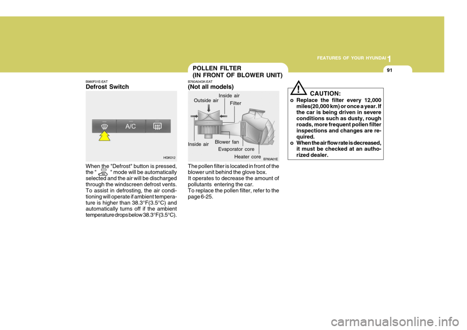
B980F01E-EAT Defrost Switch When the "Defrost" button is pressed, the " " mode will be automatically selected and the air will be dischargedthrough the windscreen defrost vents. To assist in defrosting, the air condi- tioning will operate if ambient tempera-ture is higher than 38.3°F(3.5°C) and automatically turns off if the ambient temperature drops below 38.3°F(3.5°C). B760A04GK-EAT (Not all models)
B760A01E
Evaporator core Filter
Heater core
Outside air
Inside air Inside air
Blower fan
The pollen filter is located in front of the blower unit behind the glove box. It operates to decrease the amount ofpollutants entering the car. To replace the pollen filter, refer to the page 6-25. CAUTION:
o Replace the filter every 12,000 miles(20,000 km) or once a year. If the car is being driven in severe conditions such as dusty, roughroads, more frequent pollen filter inspections and changes are re- quired.
o When the air flow rate is decreased, it must be checked at an autho-rized dealer.
!
HGK012
Page 351 of 389
6
OWNER MAINTENANCE
25
!
CHANGING THE POLLEN FILTER
G145A02GK-EAT
(In front of blower unit)(Not all models)
The pollen filter is located in front of the blower unit behind the glove box.It helps to decrease the amount ofpollutants entering the car.
2. Open the glove box and removethe mounting screws on the upside of the glove box.
1. Remove the mounting screws on the downside of the glove box. 4. Replace the pollen filter with a new
one.
5. Installation is the reverse order of disassembly.
CAUTION:
Be sure to install the pollen filter in the direction of the arrow sign. Otherwise, it may cause noise or deterioration.
HGK2111-E HGK2112-E HGK2114-E
HGK2115-E
3. Remove the filter cover.
Page 364 of 389
6OWNER MAINTENANCE
38
G270G01GK-AAT
Map Light
1. Remove the cover with a flat-blade
screwdriver.
2. Replace with a new bulb.
HGK5047
HGK5048 HGK2112-E
2. Open the glove box and remove the mounting screws on the upside of the glove box.
G270H01GK-GAT
Glove Box Illuminated Light
1. Remove the mounting screws on the downside of the glove box. HGK2111-E
HTB284
2. Remove the cover with a flat-blade
screwdriver.
3. Disconnect the power cord. HGK5046
4. Replace with a new bulb.
Page 365 of 389
6
OWNER MAINTENANCE
39
3. Remove the glove box by pulling
strongly.
CAUTION:
Be careful not to damage the glove
box when pulling the glove box.
!
HGK5052-E
HTB284
HGK5053-E
Clip
Power Cord
4. Disconnect the power cord.
5. Remove the glove box illuminated light by pushing the clip.
6. Replace with a new bulb.
Page 370 of 389

6OWNER MAINTENANCE
44
DESCRIPTIONIG COIL
AMP
B/UP LAMP
A/BAG IND A/BAG
HTD MIR HAZARD
R/WIPER TAIL-RH
F/WIPER A/C SW
RR DEFOG STOP
TAIL-LH A/CON
ECU
CLUSTER
ROOM LP
P/WINDOW
T/GATE IGN
RR FOG C/LIGHT
S/ROOF S/HTR
ABS
AUDIO
PROTECTED COMPONENTS
Ignition coil(1.6L/2.7L), Electronic chrome mirror AMP Back-up lamp switch,Transaxle range switch,Cruise control module,Stop lamp switch Instrument cluster (A/BAG IND.) SRS control module Mirror defogger Hazard relay Rear wiper motor,Rear intermittent wiper relay Right tail lamps,Glove box lamp Front wiper motor,Front wiper relay Blower relay,Blower motor Defogger relay Stop lamp switch,Burglar alarm horn relay,Folding/Unfolding relay Left tail lamps A/C control module, Blower relay ECM, Multi gauge unit, TCM, Vehicle speed sensor Instrument cluster (Power), Per-excitation resister, DRL Control module,Generator Room lamp,Clock,Audio,Data link connector,Multi gauge unit Power window relay Trunk lid switch AQS sensor,Head lamp relay,DRL Control module Rear fog lamp Cigarette lighter,Outside mirror switch Sunroof,Power door lock/Unlock relay Seat warmer ESP/ABS control module Audio,Digital clock
FUSERATING
20A20A 10A 10A 15A 10A 10A 15A 10A 20A 10A 30A 15A 10A 10A 10A 10A 10A 30A 15A 10A 10A 15A 15A 20A 10A 10A
Page 387 of 389

10
INDEX
3
F Folding rear seat ....................................................... 1-17
Front ashtray ............................................................. 1-57
Front door edge warning lamp ................................. 1-65
Front fog light switch ................................................ 1-54
Front seat adjustment ............................................... 1-12
Fuel economy ............................................................. 2-5
Fuel gauge ................................................................ 1-44
Fuel recommendations ................................................ 1-2
Fuse panel description .............................................. 6-41
Fusible links .............................................................. 6-28
GGlove box .................................................................. 1-62
H Hatchback door ......................................................... 1-67
Rear window wiper and washer ............................... 1-53
Hazard warning system ............................................ 1-55
Headlight aiming adjustment..................................... 6-31
Headlight leveling device syst em .............................1-58
Head restraint adjustment .................... ..................... 1-13
Heated rear window.................................................. 1-55
Heating and cooling control ...................................... 1-75
Rotary type ................................................ 1-76 ~ 1-83
Automatic type ........................................... 1-84 ~ 1-91
Height adjustable front seat shoulder belt ................1-20
Horn .......................................................................... 1-69I
If the engine cannot be cranked
................................ 3-2
If the engine overheats ............................................... 3-4
If the engine will not start ........................................... 3-2
If your vehicle must be towed ..................................3-12
Immobilizer system ..................................................... 1-4
Individual circuit fuses ............................................... 6-28
Instrument cluster and indicatorlight......................... 1-38
Instrument panel illumination control ........................1-37
In the event of a puncture .......................................... 3-6 J
Jump starting .............................................................. 3-3
K Key positions ............................................................... 2-3
Keys ............................................................................ 1-4 L Lighting switch .......................................................... 1-50
Luggage net .............................................................. 1-70
Lumbar support adj ustment...................................... 1-14
M Maintenance and servicing requirements ...................5-2
Maintenance under severe usage conditions ............. 5-6
Manual transaxle lubricant .......... .............................. 6-18
Manual transaxle ......................................................... 2-6
Page:
< prev 1-8 9-16 17-24