2004 Hyundai Coupe instrument panel
[x] Cancel search: instrument panelPage 65 of 389

FEATURES OF YOUR HYUNDAI 1- 57
B970C02E-GAT Automatic Operation
HGK020
The FATC (Full Automatic Temperature Control) system automatically controls heating and cool-ing as follows:
1. Push the "AUTO" switch. The indicator light will illuminate confirming that the Face, Floor and/or Bi-Level modes as well as the blowerspeed and, air conditioner will be controlledautomatically. 2. Push the "TEMP" button to set the desired
temperature.The temperature will increase to the maxi-mum 32°C(90°F) by pushing on the button.Each push of the button will cause the tem-perature to increase by 0.5°C(1°F).The temperature will decrease to the mini-mum 17°C(62°F) by pushing on the button.Each push of the button will cause the tem-perature to decrease by 0.5°C(1°F).
G280A01GK
Photo sensor
HGK014
NOTE: Never place anything over the sensor whichis located on the instrument panel to ensurebetter control of the heating and coolingsystem.
NOTE: If the battery has been discharged or discon-nected, the temperature mode will reset tocentigrade degrees.This is a normal condition and you can changethe temperature mode from centigrade tofarenheit as follows;Press the TEMP button down 3 seconds ormore with the button held down. Thedisplay shows that the unit of temperature isadjusted to centigrade or fahrenheit.(°C °F or °F °C)
OUTSIDETEMP
Page 167 of 389

INDEX
10-2
Driving
Economical driving ....................................................................... 2-11
Smooth cornering ......................................................................... 2-11
Winter driving ................................................................................ 2-11
E Emissions Control Systems ................................................................ 7-1
Engine Before starting the engine .............................................................. 2-2
Changing the oil and filter .............................................................. 6-6
Compartment .................................................................................. 6-1
Coolant ........................................................................................... 6-7
Coolant temperature gauge .......................................................... 1-29
If the engine overheats ................................................................... 3-2
Number ........................................................................................... 8-1
Oil .................................................................................................. 6-4 Oil consumption .............................................................................. 6-6
Starting ........................................................................................... 2-3
Engine Exhaust Can Be Dangerous ................................................... 2-1
FFog Li ght ........................................................................................... 1-43
Front Seats Adjustable front seats ..................................................................... 1-8
Adjustable headrests ...................................................................... 1-8Adjusting seat forward and rearward ............................................. 1-8
Adjusting seatback angle ...................... ......................................... 1-8
Lumbar support control ............... ................................................... 1-9
Seat cushion height adjustment ..................................................... 1-9
Seat warm er ................................................................................... 1-9
Fuel
Capacity .......................................................................................... 9-1
Gauge ........................................................................................... 1-28
Recommendations .......................................................................... 1-1 Fuel Filler Lid
Remote release ............................................................................ 1-45
Fuse Panel Description .......................................................... 6-23 ~ 6-24
Fuses ................................................................................................ 6-17
GGeneral Everyday Checks .................................................................. 6-4
Glove box .......................................................................................... 1-41
HHazard Warn ing System ................................................................... 1-36
Headlight Bulb ................................................................................... 6-20
Headlight Leveling Device System ................................................... 1-38
Heating and Cooling Control Rotary type ........................................................................ 1-51 ~ 1-56
Automatic type ................................................................... 1-57 ~ 1-62
High-mounted rear stoplight .............................................................. 1-44
Hood Release ................................................................................... 1-44
Horn ................................................................................................ 1-47
IIgnition Switch ..................................................................................... 2-2
Immobilizer System ............................................................................. 1-2
Infinity Sound System (B260) ........................................................... 1-80
Anti-Theft Device .......................................................................... 1-81
General operation ......................................................................... 1-81
Radio operation ............................................................................ 1-82
CD operation ................................................................................ 1-83
Instrument Cluster and Indicator ....................................................... 1-26
Instrument Panel Light Control (Rheostat) .......................................1-37
Instruments and Controls .................................................................. 1-25
Intermittent Wiper .............................................................................. 1-35
Page 179 of 389

CAUTION:
When installing a container of liquid air freshener inside the vehicle, do not place it near the instrument cluster nor on the instrument panel surface. If there is any leakage from the air freshener onto these areas (Instrument cluster, instrument panel or air ventilator), it may damage these parts. If the liquid from the air freshener does leak onto these areas, wash themwith water immediately.!
1. Passenger's Drink Holder
2. Passenger's Side Air Bag (Not all models)
3. Multi Guage (Not all models)
4. Front Fog Light Switch (Not all models)
5. Rear Fog Light Switch
6. Digital Clock
7. Hazard Warning Switch
8. Front Seat warmer (Not all models)
9. Windscreen Wiper/Washer Switch
10. Steering Wheel Tilt Lever (Not all models)
11. Multi-Function Light
12. Panel Brightness Control Knob
(Rheostat Switch) (Not all models) 13. Electronic Stability Progrem (ESP) Switch
(Not all models)
14. Headlight Leveling Device
15. Centre Console
16. Glove Box
17. Parking Brake Lever
18. Shift Lever
19. Cigarette Lighter
20. Ashtray
21. Heating/Air Conditioning Control Panel
22. Horn and Driver's Airbag
23. Cruise Control Switch (Not all models)
24. Fuse Box Relay
25. Bonnet Release Lever
Page 180 of 389

YOUR VEHICLE AT A GLANCE
B255A01GK-EAT INDICATOR SYMBOLS ON THE INSTRUMENT PANEL * More detailed explanations of these items will be found beginning on page 1-40.
Malfunction Indicator Light (Not all models)
SRS (Airbag) Service Reminder Indicator (SRI)(Not all models)
Hatchback Door Open Warning Light
Low Fuel Level Warning Light
Door Ajar Warning Light (Not all models)
ABS Service Reminder Indicator (Not all models)
Turn Signal Indicator Lights
High Beam Indicator Light Low Oil Pressure Warning Light Parking Brake/Brake Fluid Level Warning Light Charging System Warning Light
Cruise Indicator (Not all models)
Seat Belt Warning Light
CRUISE SET Indicator Light (Not all models)
Electronic Stability Program (ESP) Indicator Light (Not all models)
Immobiliser Warning Light
Page 209 of 389

1
CONTROLS AND EQUIPMENT
29
!
!
NOTE:
o Both the driver's and front
passenger's pre-tensioner seat belts will be activated in certainfrontal collisions. The pre- tensioner seat belts can be acti- vated alone or, where the frontalcollision is severe enough, to- gether with the airbags.
o When the pre-tensioner seat belts are activated, a loud noise maybe heard and fine dust, which may appear to be smoke, may bevisible in the passenger compart- ment. These are normal operat- ing conditions and are not haz-ardous.
o Although it is harmless, the fine
dust may cause skin irritationand should not be breathed for prolonged periods. Wash your hands and face thoroughly afteran accident in which the pre- tensioner seat belts were acti- vated. CAUTION:
o Because the sensor that activates the SRS airbag is connected withpre-tensioner seat belt, the SRSairbag warning light on the instrument panel will come on for approximately 6 seconds af-ter the ignition key has been turned to the "ON" position, and then it should turn off.
o If pre-tensioner seat belt is not working properly, this warninglight will illuminate even if there is no malfunction of the SRS airbag. If the SRS airbag warninglight does not illuminate when the ignition key is turned to "ON", or if it remains illuminated aftercoming for approximately 6 sec- onds, or if it illuminates while the vehicle is being driven, pleasehave an authorized Hyundai dealer inspect the pre-tensioner seat belts and SRS airbag sys-tem as soon as possible.
AIR
BAG
Their locations are shown in the illus- tration.
1. SRS airbag warning light
2. Seat belt pre-tensioner assembly
3. SRS control module
WARNING:
To obtain maximum benefit from apre-tensioner seat belt:
1. The seat belt must be worn cor- rectly.
2. The seat belt must be adjusted to
the correct position.
Page 211 of 389

1
CONTROLS AND EQUIPMENT
31
!
tection than that offered by the seat belt system alone, in case of a frontalimpact of sufficient severity. NOTE: Be sure to read information about the SRS on the labels provided onthe front side of the sun visor and in the glove box.
WARNING:
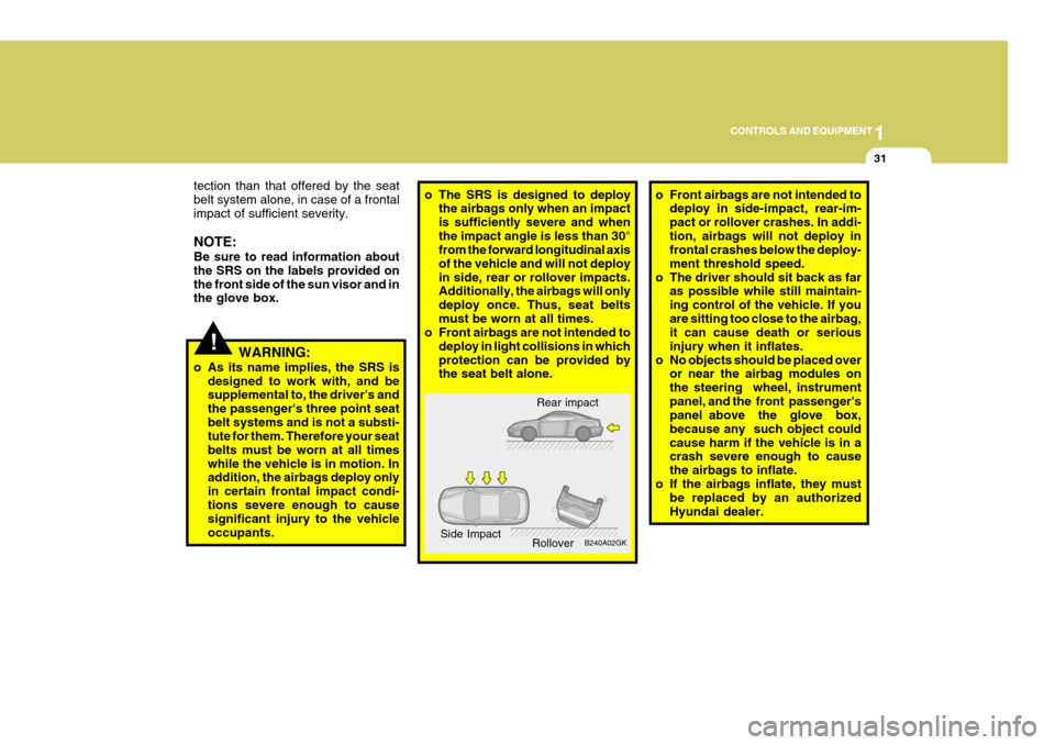
o As its name implies, the SRS is designed to work with, and besupplemental to, the driver's and the passenger's three point seatbelt systems and is not a substi- tute for them. Therefore your seat belts must be worn at all timeswhile the vehicle is in motion. In addition, the airbags deploy only in certain frontal impact condi-tions severe enough to cause significant injury to the vehicle occupants.o The SRS is designed to deploy the airbags only when an impact is sufficiently severe and whenthe impact angle is less than 30° from the forward longitudinal axis of the vehicle and will not deployin side, rear or rollover impacts. Additionally, the airbags will only deploy once. Thus, seat beltsmust be worn at all times.
o Front airbags are not intended to
deploy in light collisions in whichprotection can be provided by the seat belt alone. o Front airbags are not intended to
deploy in side-impact, rear-im- pact or rollover crashes. In addi-tion, airbags will not deploy in frontal crashes below the deploy- ment threshold speed.
o The driver should sit back as far as possible while still maintain-ing control of the vehicle. If youare sitting too close to the airbag, it can cause death or serious injury when it inflates.
o No objects should be placed over or near the airbag modules onthe steering wheel, instrumentpanel, and the front passenger's panel above the glove box, because any such object couldcause harm if the vehicle is in a crash severe enough to cause the airbags to inflate.
o If the airbags inflate, they must be replaced by an authorizedHyundai dealer.
Rear impact
B240A02GK
Side Impact
Rollover
Page 213 of 389

1
CONTROLS AND EQUIPMENT
33
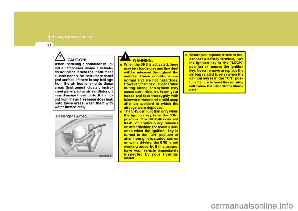
The SRS service reminder indicator (SRI) on the instrument panel will comeon for about 6 seconds after the igni- tion key is turned to the "ON" position or after the engine is started, afterwhich the SRI should go out. The airbag modules are located both in the centre of the steering wheel and in the front passenger's panel above the glove box. When the SRSCM de-tects a considerable impact to the front of the vehicle, it will automatically de- ploy the airbags. B240B02L-R Passenger's Airbag
Upon deployment, tear seams moldeddirectly into the pad covers will sepa-rate under pressure from the expan- sion of the airbags. Further opening of the covers then allows full inflation ofthe airbags. A fully inflated airbag in combination with a properly worn seat belt slows the driver's or the passenger's forward motion, thus reducing the risk of headand chest injury. After complete inflation, the airbag immediately starts deflating, enabling the driver to maintain forward visibility. B240B03L-R
B240B01GK-E
!
CAUTION:
Do not install or place any accesso- ries (drink holder, cassette holder, sticker, etc) on the front passenger'spanel above the glove box in the vehicle with passenger's side air bag. Such objects may becomedangerous projectiles and cause injury if the passenger's side air bag inflates.
Page 214 of 389

1CONTROLS AND EQUIPMENT
34
!WARNING:
o When the SRS is activated, there may be a loud noise and fine dust will be released throughout the vehicle. These conditions are normal and are not hazardous.However, the fine dust generated during airbag deployment may cause skin irritation. Wash yourhands and face thoroughly with lukewarm water and a mild soap after an accident in which theairbags were deployed.
o The SRS can function only when
the ignition key is in the "ON"position. If the SRS SRI does not flash, or continuously remains on after flashing for about 6 sec-onds when the ignition key is turned to the "ON" position or after the engine is started, comeson while driving, the SRS is not working properly. If this occurs, have your vehicle immediatelyinspected by your Hyundai dealer. o Before you replace a fuse or dis-
connect a battery terminal, turn the ignition key to the "LOCK" position or remove the ignition key. Never remove or replace theair bag related fuse(s) when the ignition key is in the "ON" posi- tion. Failure to heed this warningwill cause the SRS SRI to illumi- nate.
CAUTION:
When installing a container of liq- uid air freshener inside a vehicle, do not place it near the instrument cluster nor on the instrument panelpad surface. If there is any leakage from the air freshener onto these areas (instrument cluster, instru-ment panel pad or air ventilator), it may damage these parts. If the liq- uid from the air freshener does leakonto these areas, wash them with water immediately.!
B240B05L-R
Passenger's Airbag