Page 320 of 389

5VEHICLE MAINTENANCE REQUIREMENTS
4
DESCRIPTION ENGINE CONTROL SYSTEM MAINTENANCE ENGINE OIL & FILTER
DRIVE BELT 1.6 DOHC/2.0 DOHC CVVT (ALT, W/PUMP, P/STR'G) 2.7 V6 (AUTO-TENSIONER, ALT, P/STR'G, A/CON)
FUEL FILTER(MPI TYPE)FLUID LEAKSTIMING BELTCRANKCASE VENTILATION HOSEAIR CLEANER FILTER SPARK PLUGS (NICKEL COATED) SPARK PLUGS (PLATINUM COATED)SPARK PLUGS (IRIDIUM COATED)VALVE CLEARENCE (2.0 DOHC CVVT) 30 36
R I I I I
See Note (1) See Note (2) See Note (3) See Note (4)
NO.
1 2 3 4567 8 9
SF040A3-E In order to ensure the continued safety, reliability and longevity of the vehicle, the following maintenance service operations should be performed at the time or mileage intervals specified. It is recommended that all routine maintenance services are entrusted to a Hyundai dealer to ensure that the manufacturers recommended procedures are employed and that only genuine Hyundai replacement parts are used. Incorrect maintenance techniques or the use of non genuine replacement parts may invalidate the vehicle warranty. F030B01GK-EAT R : REPLACE I : INSPECT AND, AFTER INSPECTION, CLEAN, ADJUST, REPAIR OR REPLACE IF NECESSARY50 60
R
I I I 6072
R II I
R R
40 48
R I
R I
R
2024
R I I
R
10 12
R
I I
MILES X 1000 MONTHS
SCHEDULED MAINTENANCE
Note : (1) FOR EVERY 25,000 MILES: "R"
(2) FOR EVERY 60,000 MILES: "R"
(3) FOR EVERY 100,000 MILES: "R"
(4) FOR EVERY 60,000 MILES OR 48 MONTHS, WHICHEVER OCCURS FIRST : "I"
Page 368 of 389
6OWNER MAINTENANCE
42
PROTECTED COMPONENTS
Generator(1.6L/2.0L) BCM BOX(Tail lamp relay,Power connector,Fuse(2,7,12,13,19,20,24))Condenser fan relayRadiator fan relayEngine control relay, Fuel pump relay, A/T control relay, Generator,ECM(1.6L/2.7L),PCM(2.0L) Ignition switch,Start relayABS/ESP control module,ESP Air bleeding connectorABS/ESP control module,ESP Air bleeding connectorBlower relayInjector Oxygen sensor,Camshaft position sensor, Idle speed control actuator DRL control moduleFront fog lamp relayTCM(2.7L),ECM(2.7L/1.6L)Horn relay,A/C relay Head lamp relay(High) Head lamp relay(Low)
FUSERATING 120A50A 30A30A 30A 30A 40A40A30A 15A 10A15A15A10A15A 15A 15A
DESCRIPTION
BATTBATT
COND RAD ECU
IGN
ABS 1 ABS 2
BLOWER INJ
SNSR DRL
F/FOG ECU
HORN,A/CON H/LP (HI)
H/LP (LO)
Page 373 of 389

7
EMISSION CONTROL SYSTEMS
3CATALYTIC CONVERTOR
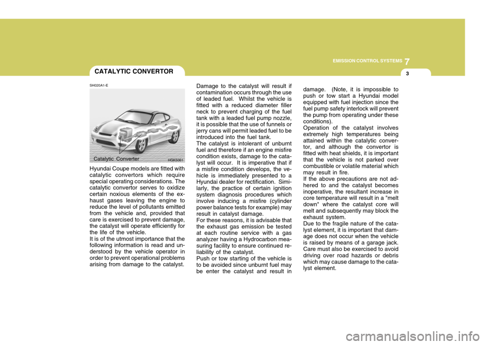
SH020A1-E Hyundai Coupe models are fitted with catalytic convertors which requirespecial operating considerations. The catalytic convertor serves to oxidize certain noxious elements of the ex-haust gases leaving the engine to reduce the level of pollutants emitted from the vehicle and, provided thatcare is exercised to prevent damage, the catalyst will operate efficiently for the life of the vehicle. It is of the utmost importance that the following information is read and un- derstood by the vehicle operator inorder to prevent operational problems arising from damage to the catalyst. Damage to the catalyst will result if contamination occurs through the useof leaded fuel. Whilst the vehicle is fitted with a reduced diameter filler neck to prevent charging of the fueltank with a leaded fuel pump nozzle, it is possible that the use of funnels or jerry cans will permit leaded fuel to beintroduced into the fuel tank.The catalyst is intolerant of unburntfuel and therefore if an engine misfirecondition exists, damage to the cata- lyst will occur. It is imperative that if a misfire condition develops, the ve-hicle is immediately presented to a Hyundai dealer for rectification. Simi- larly, the practice of certain ignitionsystem diagnosis procedures which involve inducing a misfire (cylinder power balance tests for example) mayresult in catalyst damage.For these reasons, it is advisable thatthe exhaust gas emission be tested at each routine service with a gas analyzer having a Hydrocarbon mea-suring facility to ensure continued re- liability of the catalyst. Push or tow starting of the vehicle is to be avoided since unburnt fuel may be enter the catalyst and result in
Catalytic Converter
HGK5061 damage. (Note, it is impossible to push or tow start a Hyundai modelequipped with fuel injection since the fuel pump safety interlock will prevent the pump from operating under theseconditions).Operation of the catalyst involvesextremely high temperatures beingattained within the catalytic conver- tor, and although the convertor is fitted with heat shields, it is importantthat the vehicle is not parked over combustible or volatile material which may result in fire.If the above precautions are not ad-hered to and the catalyst becomesinoperative, the resultant increase in core temperature will result in a "melt down" where the catalyst core willmelt and subsequently may block the exhaust system. Due to the fragile nature of the cata- lyst element, it is important that dam- age does not occur when the vehicleis raised by means of a garage jack. Care must also be exercised to avoid driving over road hazards or debriswhich may cause damage to the cata- lyst element.
Page 382 of 389
9 VEHICLE SPECIFICATIONS
2
J010A01GK-EAT MEASUREMENT 173(4395)
69.3(1760) 52.4(1330) 99.6(2530)58.7(1490) 58.7(1490)
Overall length Overall width Overall height (unladen)Wheel base Wheel tread FrontRear
Type Wheel free play Rack strokeOil pump type Rack and pinion0 ~ 1.18 in. (0 ~ 30 mm) 5.20 in. (132 mm) Vane type
Option
Item Battery Alternator
in. (mm)
Fuel tank
capacity Imp.gal
12 2.7L
MF 68AH
120A
195/65 R15, 205/55 R16, 215/45 R17
2.0L
MF 68AH 90A
Dual hydraulic with brake booster Ventilated disc Solid discCable
Type Front brake type Rear brake typeParking brake
US.gal
14.5Liter55
Standard T125/70 R16 (Temporary)
1.6L
MF 60AH
90A
SJ030A1-E FUEL SYSTEM
J020A01GK-EATPOWER STEERING J030A01GK-EAT TYRE J040A03GK-GAT ELECTRICAL
J050A01GK-GAT BRAKE
J035A01GK-DATSPARE TYRE