Page 347 of 389
6
OWNER MAINTENANCE
21
HGK5008
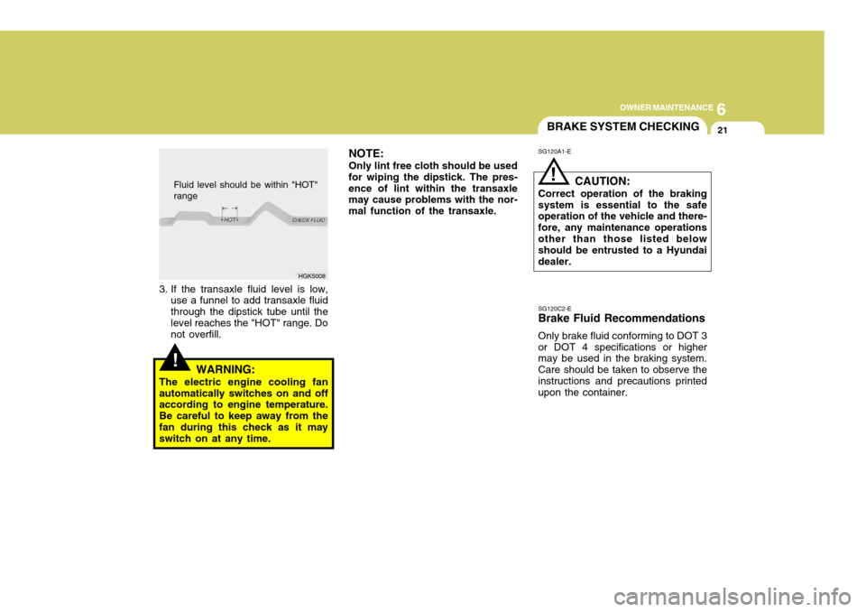
Fluid level should be within "HOT" range
!
SG120A1-E
BRAKE SYSTEM CHECKING
CAUTION:
Correct operation of the braking system is essential to the safe operation of the vehicle and there- fore, any maintenance operationsother than those listed below should be entrusted to a Hyundai dealer.
NOTE: Only lint free cloth should be used
for wiping the dipstick. The pres- ence of lint within the transaxle may cause problems with the nor- mal function of the transaxle.
3. If the transaxle fluid level is low, use a funnel to add transaxle fluidthrough the dipstick tube until thelevel reaches the "HOT" range. Do not overfill.
!WARNING:
The electric engine cooling fan automatically switches on and off according to engine temperature. Be careful to keep away from thefan during this check as it may switch on at any time. SG120C2-E Brake Fluid Recommendations Only brake fluid conforming to DOT 3 or DOT 4 specifications or higher may be used in the braking system. Care should be taken to observe theinstructions and precautions printed upon the container.
Page 349 of 389
6
OWNER MAINTENANCE
23
!
SG130B2-E
Adding Fluid
Recommended brake fluid conform-
ing to DOT 3 or DOT 4 should be used. The reservoir cap must be fully tightened to avoid contamination fromforeign matter or moisture.
WARNING:
Brake fluid will cause rapid and
serious damage to paintwork. Ifaccidental spillage occurs, the af-fected area must be rinsed with water immediately. Do not allow brake fluid to come into contactwith the eyes or to be ingested and ensure that fluid is safely stored away form the reach of children. SG140A1-E
Condenser
Ensure that the condenser is periodi-cally inspected and that accumula- tions of dirt, dead insects and leaves etc, are removed to ensure that theefficiency of the system is not im- paired. Care must be exercised to ensure that the condenser fins arenot damaged during cleaning. AIR CONDITIONING SYSTEM MAINTENANCE
!
SG140C2-E
Checking the Refrigerant
1. Start the engine and run at idle for
several minutes with the refrigera- tion system running at the coldest setting.
2. If the air coming out of the in-dash vents is not cold, have the air con-ditioning system inspected by your Hyundai dealer.
CAUTION:
Running the air conditioning sys-
tem for extended periods of time with a low refrigerant level maydamage the compressor.
CAUTION:
Brake fluid is hygroscopic andshould never be stored in an un-sealed container. Do not allow petroleum base fluid to contami- nate the brake fluid since damageto the rubber seals of the system may result.
!
Page 352 of 389
6OWNER MAINTENANCE
26CHECKING THE FREE-PLAY
SG150A1-E STEERING WHEEL Steering wheel freeplay should be checked to ensure that the specifiedvalue is not exceeded. 1.18in. (30 mm)SG160A1-E
CLUTCH PEDAL
The clutch pedal freeplay should be
checked against the specified value. If the freeplay is not correct, the clutch should be adjusted by a Hyundai dealer. 0.24 ~ 0.51 in. (6 ~ 13 mm)
SG170A1-E
BRAKE PEDAL
The brake pedal freeplay should be
checked with the engine turned off. The pedal to floor clearance should be checked with the engine running and a load of 490 N applied to thepedal. If either value is incorrect, the necessary adjustment should be per- formed by a Hyundai dealer. Pedal tofloor clearance: 1.97 in. (50 mm) 0.12 ~ 0.31 in. (3 ~ 8 mm)
HGK5019 G160A01E HXGS508
Page 353 of 389
6
OWNER MAINTENANCE
27CHECKING BRAKE PEDAL CLEARANCE
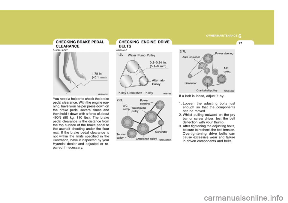
G180A01A-EAT You need a helper to check the brake pedal clearance. With the engine run- ning, have your helper press down onthe brake pedal several times and then hold it down with a force of about 490N (50 kg, 110 lbs). The brakepedal clearance is the distance from the top surface of the brake pedal to the asphalt sheeting under the floormat. If the brake pedal clearance is not within the limits specified in the illustration, have it inspected by yourHyundai dealer and adjusted or re- paired if necessary. 1.78 in.(45.1 mm)
YG190A1-E
CHECKING ENGINE DRIVE BELTS
If a belt is loose, adjust it by:
1. Loosen the adusting bolts justenough so that the components can be moved.
2. Whilst pulling outward on the pry bar or screw driver, test the beltdeflection with your thumb.
3. After tightening the adjusting bolts,
be sure to recheck the belt tension.Overtightening drive belts can cause excessive wear and failure in driven components and belts.
G180A01L
Tension pulleyGenerator
G190A01GK
Power steering
Water pump pulley
A/Ccomp.
2.0L G190A02B
A/C comp.
Crankshaft pulley
Power steering
Auto tensioner
Generator
2.7LWater Pump Pulley
Alternator Pulley
Pulley Crankshaft Pulley 0.2~0.24 in.(5.1~6 mm)
HTB186
1.6L
Crankshaft pulley
Page 356 of 389
6OWNER MAINTENANCE
30
o If battery electrolyte is spilled onto
skin or into eyes, the effected area must be flushed with copious amounts of water and medical assis-tance sought.
o If battery electrolyte is ingested, copious amounts of water or milkfollowed by an ant-acid (raw egg ormilk of magnesia) must be drunk. Vomiting should not be induced and medical assistance must besought.
o Batteries must only be charged in well venti-lated areas from which naked lights or sources of sparks are excluded.
o Ensure that children, pets or other unautho-rized persons are keptaway from batteries.
o Do not allow anything to bridge the
positive (+) and negative (-) termi-nals of the battery.
o Never invert the battery.
The battery fitted during production isof the "Maintenance Free" type.
ELECTRIC COOLING FANS
!
YG210A1-E
WARNING:
The cooling fan is controlled by engine coolant temperature and may sometimes operate even whenthe engine is not running. Do not touch the radiator fan until it is completely stopped.As the coolant temperature de-creases the fan will automaticallyshut off. This is a normal condi- tion.
Checking Engine Cooling Fan The engine cooling fan should auto- matically come on if the engine cool-ant temperature is high.
Checking Condenser Cooling Fan The condenser cooling fan (in front of the condenser) should come on auto- matically whenever the air conditioneris in operation.
POWER STEERING HOSES
YG220A1-E It is suggested that you check the power steering hose connections for fluid leakage at those intervals speci- fied in the vehicle maintenance sched-ule in Section 5. The power steering hoses should be replaced if there are severe surface cracking, pulling, scuff-ing or worn spots. Deterioration of the hoses could cause premature failure. NOTE: The power steering pump may be noisy when the engine is firststarted in the extreme cold (-4°F). This noise is not abnormal and will stop as the engine warms up.If the power steering pump contin- ues to be noisy after the engine has warmed up, have it inspectedby your Authorized Hyundai Dealer.
Page 357 of 389
6
OWNER MAINTENANCE
31
HGK5011
G230A03A-EAT
Power Steering Fluid Level Fluid Recommendation
Only automatic transaxle fluid meet-
ing the specification of PSF-3 or ATF DEXRON 2 should be used in thepower steering system.
The power steering fluid level should
be checked regularly.
To check the power steering fluid
level, be sure the ignition is "OFF",then check to make certain that thepower steering fluid level is between the "MAX" and "MIN" level markings on the fluid reservoir.
NOTE: Do not check whilst the engine is
running. Do not start when power steering fluid reservoir is empty.High Beam
G290A01GK
G290A01GK-EAT HEADLIGHT AIMING AD- JUSTMENT
Before performing aiming adjustment, make sure of the following.
G290A02GK
Low Beam
Horizontal aiming Verticalaiming
Horizontal aiming Vertical aiming
Page 358 of 389
6OWNER MAINTENANCE
32
G290B01GK-EAT
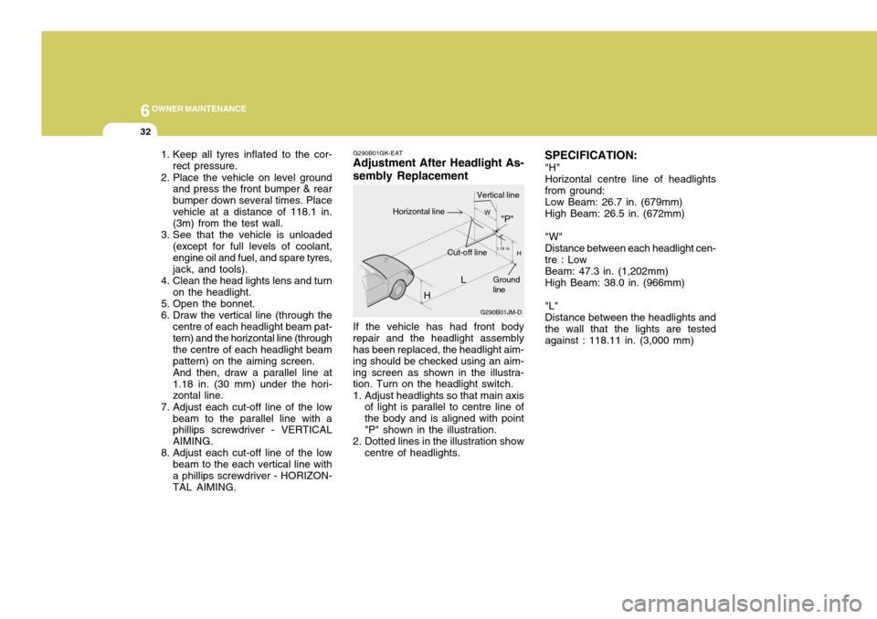
Adjustment After Headlight As- sembly Replacement
If the vehicle has had front body
repair and the headlight assembly has been replaced, the headlight aim- ing should be checked using an aim-ing screen as shown in the illustra- tion. Turn on the headlight switch.
1. Adjust headlights so that main axis of light is parallel to centre line of the body and is aligned with point"P" shown in the illustration.
2. Dotted lines in the illustration show centre of headlights. SPECIFICATION:
"H" Horizontal centre line of headlights from ground: Low Beam: 26.7 in. (679mm) High Beam: 26.5 in. (672mm) "W" Distance between each headlight cen- tre : Low Beam: 47.3 in. (1,202mm) High Beam: 38.0 in. (966mm) "L" Distance between the headlights and the wall that the lights are tested against : 118.11 in. (3,000 mm)
1. Keep all tyres inflated to the cor-
rect pressure.
2. Place the vehicle on level ground and press the front bumper & rearbumper down several times. Placevehicle at a distance of 118.1 in. (3m) from the test wall.
3. See that the vehicle is unloaded (except for full levels of coolant, engine oil and fuel, and spare tyres,jack, and tools).
4. Clean the head lights lens and turn on the headlight.
5. Open the bonnet.
6. Draw the vertical line (through the centre of each headlight beam pat- tern) and the horizontal line (through the centre of each headlight beampattern) on the aiming screen.And then, draw a parallel line at1.18 in. (30 mm) under the hori- zontal line.
7. Adjust each cut-off line of the low beam to the parallel line with aphillips screwdriver - VERTICAL AIMING.
8. Adjust each cut-off line of the low beam to the each vertical line witha phillips screwdriver - HORIZON- TAL AIMING. L
G290B01JM-D
W
H
H Cut-off line"P"
Vertical lineHorizontal line
Ground line
1.18 in.
Page 383 of 389
9
VEHICLE SPECIFICATIONS
3
2.0 L
82 x 93.5 1,975
1 - 3 - 4 - 2
0.0067 ~ 0.0091 in. (0.17 ~ 0.23 mm) 0.0098 ~ 0.0122 in. (0.25 ~ 0.31 mm)
0.0047 ~ 0.011 in. (0.12 ~ 0.28 mm) 0.0079 ~ 0.015 in. (0.2 ~ 0.38 mm)
� �
700 ± 100
BTDC 8° ± 5° 2.7 L
6-Cyl., V-type DOHC 86.7 x 75
2,656
1 - 2 - 3 - 4 - 5 - 6
AUTO LASH
PFR5N-11, IFR5G-11 RC10PYPB4
750 ± 100
BTDC 12° ± 10°
4-Cyl., In-line DOHC
1.6 L
76.5 x 87 1,599
1 - 3 - 4 - 2
AUTO LASH
BKR5ES-11 RC10YC4
700 ± 100
BTDC 5° ± 5°
ITEMS
Engine Type Bore x Stroke (mm) Displacement (cc) Firing order Valve clearance (Cold Engine 20 ± 5°C) Spark plug Spark plug gap Idle speed (rpm) Ignition timing (Base)
For adjustingFor checking NGKCHAMPION IntakeExhaustIntake Exhaust
ENGINE
J070A04GK-EAT SPECIFICATION
0.039 ~ 0.043 in. (1.0 ~ 1.1 mm)