2004 FORD F150 height
[x] Cancel search: heightPage 46 of 248
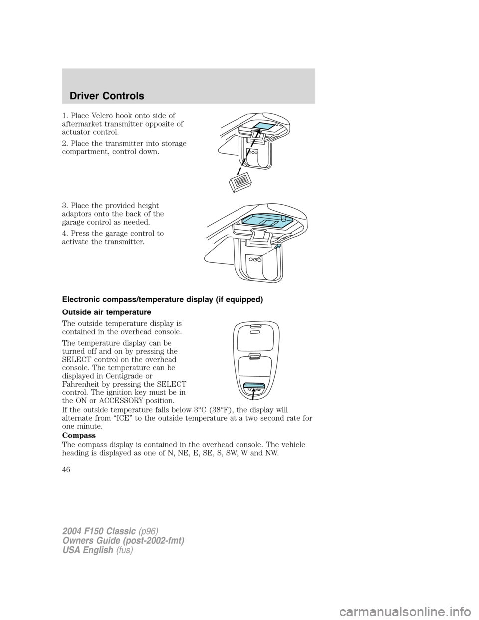
1. Place Velcro hook onto side of
aftermarket transmitter opposite of
actuator control.
2. Place the transmitter into storage
compartment, control down.
3. Place the provided height
adaptors onto the back of the
garage control as needed.
4. Press the garage control to
activate the transmitter.
Electronic compass/temperature display (if equipped)
Outside air temperature
The outside temperature display is
contained in the overhead console.
The temperature display can be
turned off and on by pressing the
SELECT control on the overhead
console. The temperature can be
displayed in Centigrade or
Fahrenheit by pressing the SELECT
control. The ignition key must be in
the ON or ACCESSORY position.
If the outside temperature falls below 3°C (38°F), the display will
alternate from“ICE”to the outside temperature at a two second rate for
one minute.
Compass
The compass display is contained in the overhead console. The vehicle
heading is displayed as one of N, NE, E, SE, S, SW, W and NW.
73˚ NW
2004 F150 Classic(p96)
Owners Guide (post-2002-fmt)
USA English(fus)
Driver Controls
46
Page 74 of 248
3. Allow the belt to retract. As the belt retracts, you will hear a clicking
sound. This indicates the safety belt is now in the automatic locking
mode.
How to disengage the automatic locking mode
Disconnect the combination lap/shoulder belt and allow it to retract
completely to disengage the automatic locking mode and activate the
vehicle sensitive (emergency) locking mode.
After any vehicle collision, the safety belt systems at all outboard
seating positions (except the driver position, which does not
have this feature) must be checked by a qualified technician to verify
that the automatic locking retractor feature for child seats is still
functioning properly. In addition, all seat belts should be checked for
proper function.
BELT AND RETRACTOR ASSEMBLY MUST BE REPLACED if
the seat belt assembly“automatic locking retractor”feature or
any other seat belt function is not operating properly when checked
according to the procedures in Workshop Manual. Failure to replace
the Belt and Retractor assembly could increase the risk of injury in
collisions.
Safety belt pretensioner
Your vehicle is equipped with safety belt pretensioners at the driver and
front outboard passenger seating positions.
The driver and front outboard passenger safety belt pretensioners are
designed to activate only during certain frontal or near-frontal collisions
with sufficient longitudinal deceleration. A safety belt pretensioner is a
device which tightens the webbing of the lap and shoulder belts during
some collisions in such a way that they fit more snugly against the body.
The driver and front outboard passenger safety belt system (including
retractors, buckles and height adjusters) must be replaced if the vehicle
is involved in a collision that results in the activation of the safety belt
pretensioners. Refer to theSafety belt maintenancesection in this
chapter.
Failure to replace the safety belt assembly under the above
conditions could result in severe personal injuries in the event of
a collision.
2004 F150 Classic(p96)
Owners Guide (post-2002-fmt)
USA English(fus)
Seating and Safety Restraints
74
Page 75 of 248
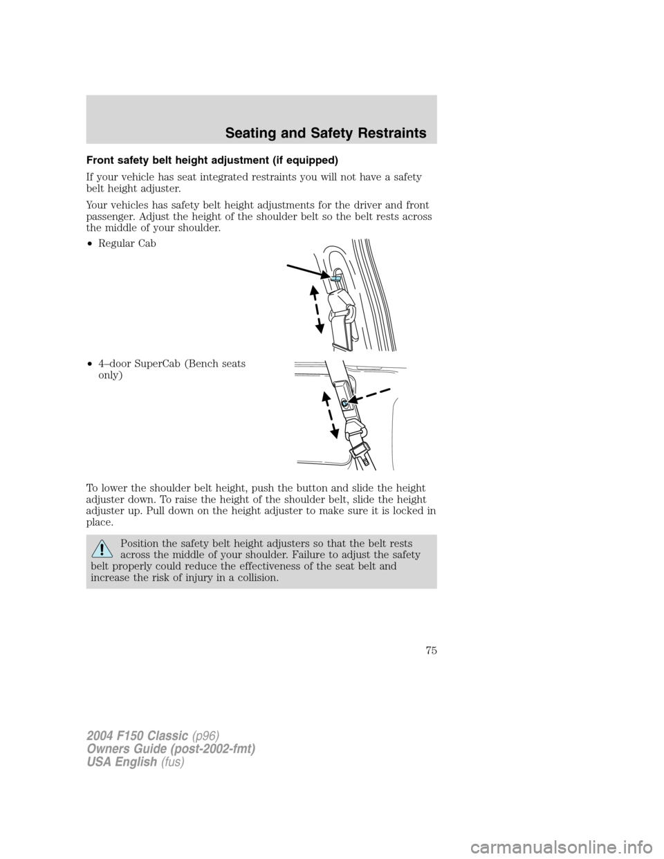
Front safety belt height adjustment (if equipped)
If your vehicle has seat integrated restraints you will not have a safety
belt height adjuster.
Your vehicles has safety belt height adjustments for the driver and front
passenger. Adjust the height of the shoulder belt so the belt rests across
the middle of your shoulder.
•Regular Cab
•4–door SuperCab (Bench seats
only)
To lower the shoulder belt height, push the button and slide the height
adjuster down. To raise the height of the shoulder belt, slide the height
adjuster up. Pull down on the height adjuster to make sure it is locked in
place.
Position the safety belt height adjusters so that the belt rests
across the middle of your shoulder. Failure to adjust the safety
belt properly could reduce the effectiveness of the seat belt and
increase the risk of injury in a collision.
2004 F150 Classic(p96)
Owners Guide (post-2002-fmt)
USA English(fus)
Seating and Safety Restraints
75
Page 81 of 248
Safety belt extension assembly
If the safety belt is too short when fully extended, there is a 8 inch (20
cm) safety belt extension assembly that can be added (part number
611C22). This assembly can be obtained from your dealer at no cost.
Use only extensions manufactured by the same supplier as the safety
belt. Manufacturer identification is located at the end of the webbing on
the label. Also, use the safety belt extension only if the safety belt is too
short for you when fully extended.
Do not use extensions to change the fit of the shoulder belt
across the torso.
Safety belt maintenance
Inspect the safety belt systems periodically to make sure they work
properly and are not damaged. Inspect the safety belts to make sure
there are no nicks, tears or cuts. Replace if necessary. All safety belt
assemblies, including retractors, buckles, front seat belt buckle
assemblies, buckle support assemblies (slide bar-if equipped), shoulder
belt height adjusters (if equipped), shoulder belt guide on seatback (if
equipped), child safety seat LATCH and tether anchors, and attaching
hardware, should be inspected after a collision. Ford Motor Company
recommends that all safety belt assemblies in use in vehicles involved in
a collision be replaced. However, if the collision was minor and a
qualified technician finds that the belts do not show damage and
continue to operate properly, they do not need to be replaced. Safety
belt assemblies not in use during a collision should also be inspected and
replaced if either damage or improper operation is noted.
Failure to inspect and if necessary replace the safety belt
assembly under the above conditions could result in severe
personal injuries in the event of a collision.
Refer toInteriorin theCleaningchapter.
2004 F150 Classic(p96)
Owners Guide (post-2002-fmt)
USA English(fus)
Seating and Safety Restraints
81
Page 137 of 248
Hitches
Do not use hitches that clamp onto the vehicle’s bumper or attach to the
axle. You must distribute the load in your trailer so that 10%–15% of the
total weight of the trailer is on the tongue.
Load equalizing hitch
When hooking up a trailer using a load equalizing hitch, always use the
following procedure:
1. Park the unloaded vehicle on a level surface. With the ignition on and
all doors closed, allow the vehicle to stand for several minutes so that it
can level.
2. Measure the height of a reference point on the front and rear bumpers
at the center of the vehicle.
3. Attach the trailer to the vehicle and adjust the hitch equalizers so that
the front bumper height is within
1⁄2”(13 mm) of the reference point.
After proper adjustment, the rear bumper should be no higher than in
Step 2.
Note:Adjusting an equalizing hitch so the rear bumper of the vehicle is
higher than it was unloaded will defeat the function of the load
equalizing hitch and may cause unpredictable handling.
Safety chains
Always connect the trailer’s safety chains to the frame or hook retainers
of the vehicle hitch. To connect the trailer’s safety chains, cross the
chains under the trailer tongue and allow slack for turning corners.
If you use a rental trailer, follow the instructions that the rental agency
gives to you.
Do not attach safety chains to the bumper.
Trailer brakes
Electric brakes and manual, automatic or surge-type trailer brakes are
safe if installed properly and adjusted to the manufacturer’s
specifications. The trailer brakes must meet local and Federal
regulations.
Do not connect a trailer’s hydraulic brake system directly to your
vehicle’s brake system. Your vehicle may not have enough
braking power and your chances of having a collision greatly increase.
2004 F150 Classic(p96)
Owners Guide (post-2002-fmt)
USA English(fus)
Driving
137
Page 217 of 248
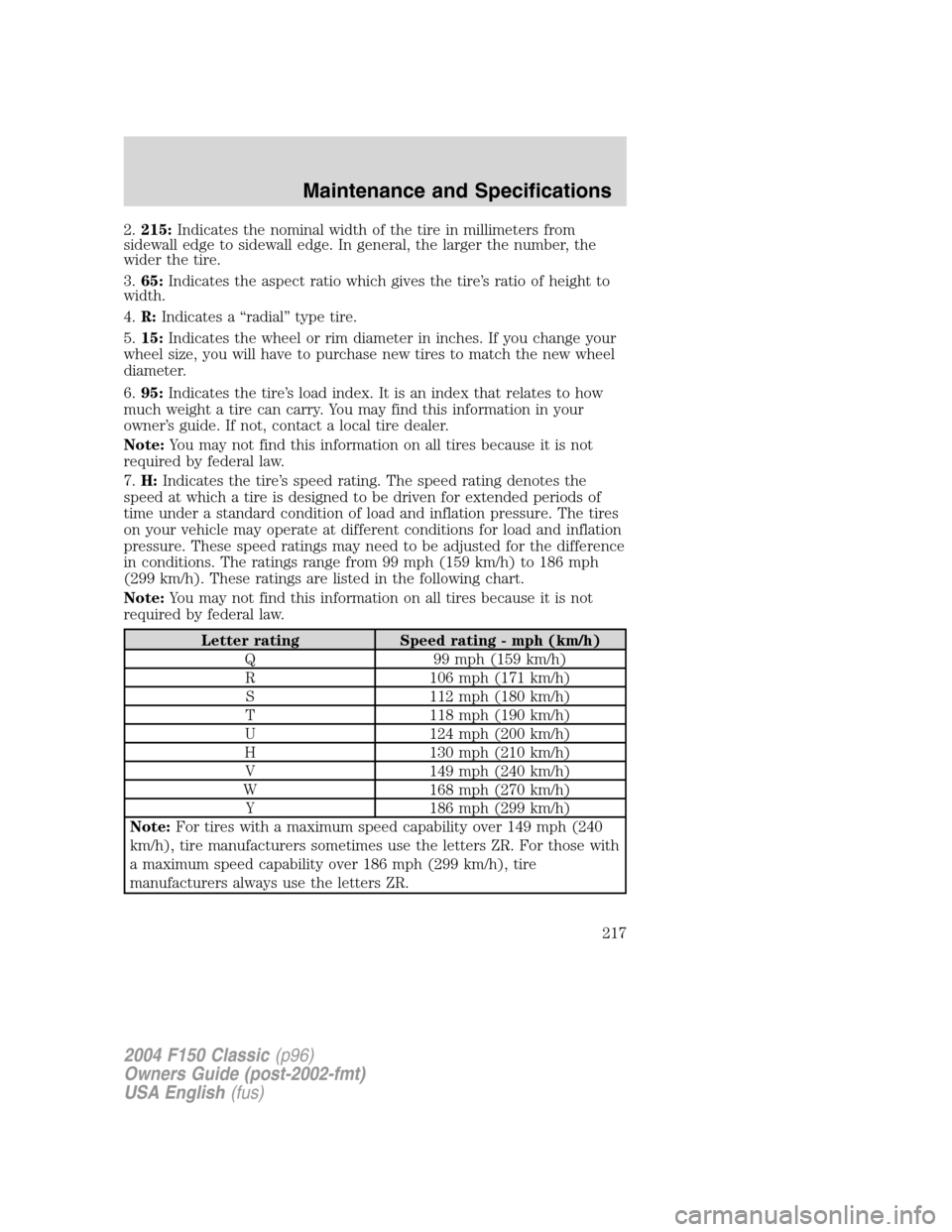
2.215:Indicates the nominal width of the tire in millimeters from
sidewall edge to sidewall edge. In general, the larger the number, the
wider the tire.
3.65:Indicates the aspect ratio which gives the tire’s ratio of height to
width.
4.R:Indicates a“radial”type tire.
5.15:Indicates the wheel or rim diameter in inches. If you change your
wheel size, you will have to purchase new tires to match the new wheel
diameter.
6.95:Indicates the tire’s load index. It is an index that relates to how
much weight a tire can carry. You may find this information in your
owner’s guide. If not, contact a local tire dealer.
Note:You may not find this information on all tires because it is not
required by federal law.
7.H:Indicates the tire’s speed rating. The speed rating denotes the
speed at which a tire is designed to be driven for extended periods of
time under a standard condition of load and inflation pressure. The tires
on your vehicle may operate at different conditions for load and inflation
pressure. These speed ratings may need to be adjusted for the difference
in conditions. The ratings range from 99 mph (159 km/h) to 186 mph
(299 km/h). These ratings are listed in the following chart.
Note:You may not find this information on all tires because it is not
required by federal law.
Letter rating Speed rating - mph (km/h)
Q 99 mph (159 km/h)
R 106 mph (171 km/h)
S 112 mph (180 km/h)
T 118 mph (190 km/h)
U 124 mph (200 km/h)
H 130 mph (210 km/h)
V 149 mph (240 km/h)
W 168 mph (270 km/h)
Y 186 mph (299 km/h)
Note:For tires with a maximum speed capability over 149 mph (240
km/h), tire manufacturers sometimes use the letters ZR. For those with
a maximum speed capability over 186 mph (299 km/h), tire
manufacturers always use the letters ZR.
2004 F150 Classic(p96)
Owners Guide (post-2002-fmt)
USA English(fus)
Maintenance and Specifications
217
Page 220 of 248
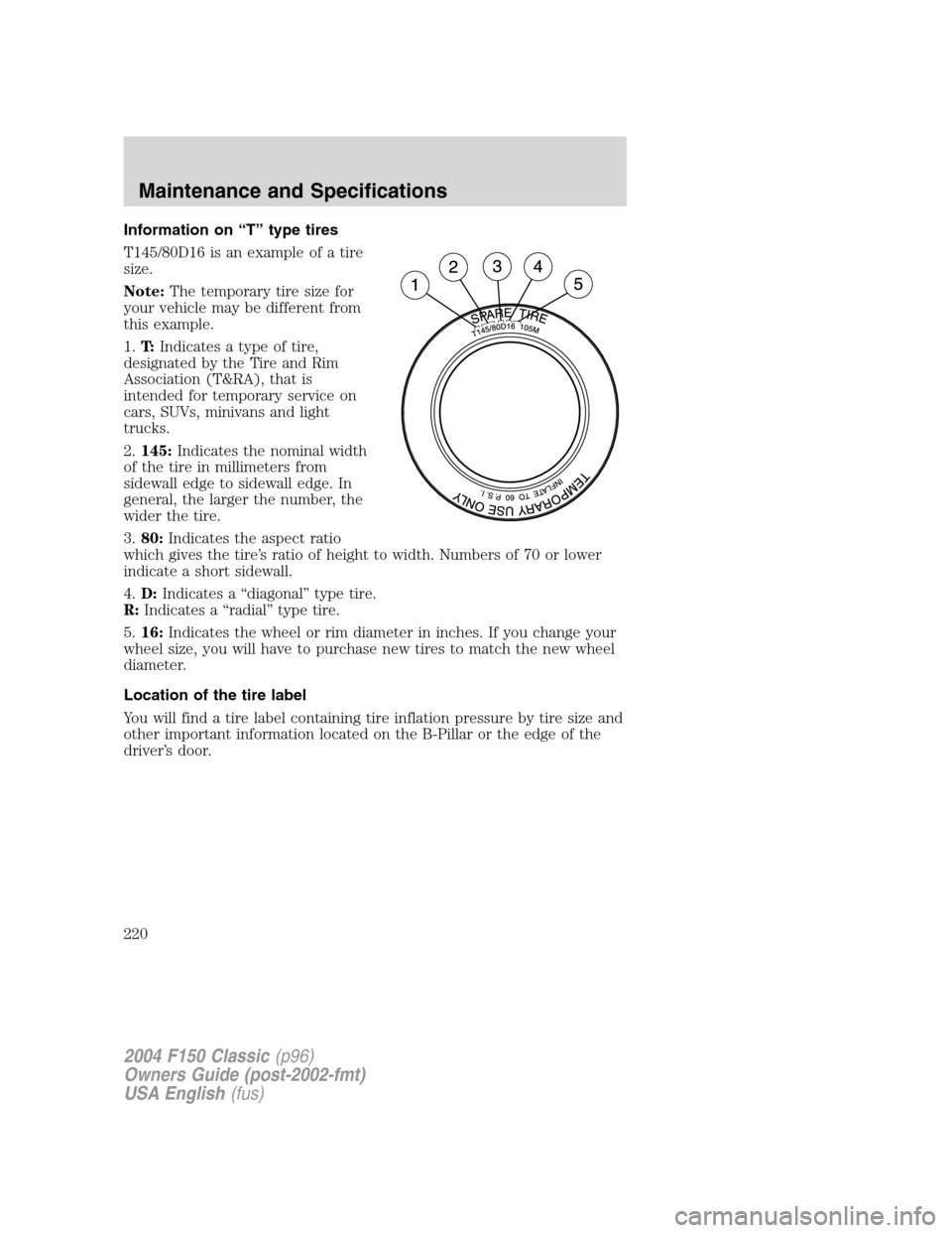
Information on“T”type tires
T145/80D16 is an example of a tire
size.
Note:The temporary tire size for
your vehicle may be different from
this example.
1.T:Indicates a type of tire,
designated by the Tire and Rim
Association (T&RA), that is
intended for temporary service on
cars, SUVs, minivans and light
trucks.
2.145:Indicates the nominal width
of the tire in millimeters from
sidewall edge to sidewall edge. In
general, the larger the number, the
wider the tire.
3.80:Indicates the aspect ratio
which gives the tire’s ratio of height to width. Numbers of 70 or lower
indicate a short sidewall.
4.D:Indicates a“diagonal”type tire.
R:Indicates a“radial”type tire.
5.16:Indicates the wheel or rim diameter in inches. If you change your
wheel size, you will have to purchase new tires to match the new wheel
diameter.
Location of the tire label
You will find a tire label containing tire inflation pressure by tire size and
other important information located on the B-Pillar or the edge of the
driver’s door.
2004 F150 Classic(p96)
Owners Guide (post-2002-fmt)
USA English(fus)
Maintenance and Specifications
220
Page 234 of 248
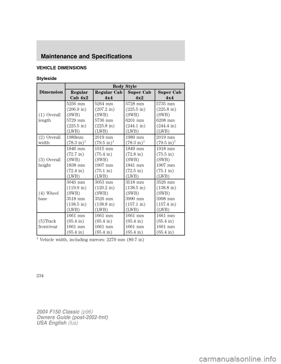
VEHICLE DIMENSIONS
Styleside
DimensionBody Style
Regular
Cab 4x2Regular Cab
4x4Super Cab
4x2Super Cab
4x4
(1) Overall
length5256 mm
(206.9 in)
(SWB)
5729 mm
(225.5 in)
(LWB)5264 mm
(207.2 in)
(SWB)
5736 mm
(225.8 in)
(LWB)5728 mm
(225.5 in)
(SWB)
6201 mm
(244.1 in)
(LWB)5735 mm
(225.8 in)
(SWB)
6208 mm
(244.4 in)
(LWB)
(2) Overall
width1989mm
(78.3 in)
12019 mm
(79.5 in)11989 mm
(78.3 in)12019 mm
(79.5 in)1
(3) Overall
height1846 mm
(72.7 in)
(SWB)
1838 mm
(72.4 in)
(LWB)1915 mm
(75.4 in)
(SWB)
1907 mm
(75.1 in)
(LWB)1849 mm
(72.8 in)
(SWB)
1841 mm
(72.5 in)
(LWB)1918 mm
(75.5 in)
(SWB)
1907 mm
(75.1 in)
(LWB)
(4) Wheel
base3045 mm
(119.9 in)
(SWB)
3518 mm
(138.5 in)
(LWB)3053 mm
(120.2 in)
(SWB)
3526 mm
(138.8 in)
(LWB)3518 mm
(138.5 in)
(SWB)
3990 mm
(157.1 in)
(LWB)3526 mm
(138.8 in)
(SWB)
3998 mm
(157.4 in)
(LWB)
(5)Track
front/rear1661 mm
(65.4 in)
1661 mm
(65.4 in)1661 mm
(65.4 in)
1661 mm
(65.4 in)1661 mm
(65.4 in)
1661 mm
(65.4 in)1661 mm
(65.4 in)
1661 mm
(65.4 in)
1Vehicle width, including mirrors: 2279 mm (89.7 in)
2004 F150 Classic(p96)
Owners Guide (post-2002-fmt)
USA English(fus)
Maintenance and Specifications
234