Page 136 of 248
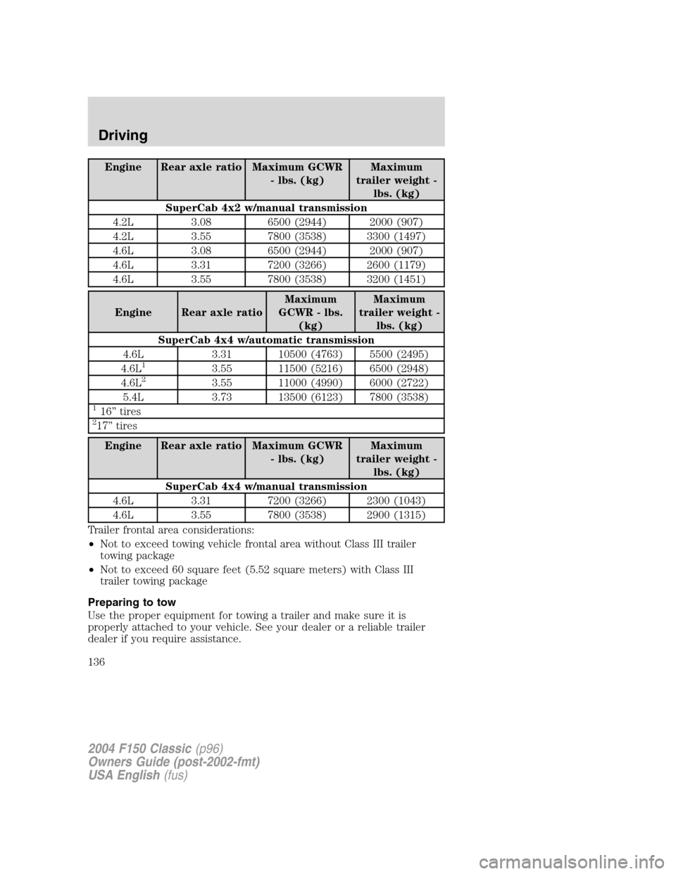
Engine Rear axle ratio Maximum GCWR
- lbs. (kg)Maximum
trailer weight -
lbs. (kg)
SuperCab 4x2 w/manual transmission
4.2L 3.08 6500 (2944) 2000 (907)
4.2L 3.55 7800 (3538) 3300 (1497)
4.6L 3.08 6500 (2944) 2000 (907)
4.6L 3.31 7200 (3266) 2600 (1179)
4.6L 3.55 7800 (3538) 3200 (1451)
Engine Rear axle ratioMaximum
GCWR - lbs.
(kg)Maximum
trailer weight -
lbs. (kg)
SuperCab 4x4 w/automatic transmission
4.6L 3.31 10500 (4763) 5500 (2495)
4.6L
13.55 11500 (5216) 6500 (2948)
4.6L23.55 11000 (4990) 6000 (2722)
5.4L 3.73 13500 (6123) 7800 (3538)
116”tires217”tires
Engine Rear axle ratio Maximum GCWR
- lbs. (kg)Maximum
trailer weight -
lbs. (kg)
SuperCab 4x4 w/manual transmission
4.6L 3.31 7200 (3266) 2300 (1043)
4.6L 3.55 7800 (3538) 2900 (1315)
Trailer frontal area considerations:
•Not to exceed towing vehicle frontal area without Class III trailer
towing package
•Not to exceed 60 square feet (5.52 square meters) with Class III
trailer towing package
Preparing to tow
Use the proper equipment for towing a trailer and make sure it is
properly attached to your vehicle. See your dealer or a reliable trailer
dealer if you require assistance.
2004 F150 Classic(p96)
Owners Guide (post-2002-fmt)
USA English(fus)
Driving
136
Page 139 of 248
Trailer towing tips
•Practice turning, stopping and backing up before starting on a trip to
get the feel of the vehicle trailer combination. When turning, make
wider turns so the trailer wheels will clear curbs and other obstacles.
•Allow more distance for stopping with a trailer attached.
•The trailer tongue weight should be 10–15% of the loaded trailer
weight.
•After you have traveled 50 miles (80 km), thoroughly check your
hitch, electrical connections and trailer wheel lug nuts.
•To aid in engine/transmission cooling and A/C efficiency during hot
weather while stopped in traffic, place the gearshift lever in P (Park)
(automatic transmission) or N (Neutral) (manual transmissions).
•Vehicles with trailers should not be parked on a grade. If you must
park on a grade, place wheel chocks under the trailer’s wheels.
Launching or retrieving a boat
Disconnect the wiring to the trailer before backing the trailer
into the water. Reconnect the wiring to the trailer after the
trailer is removed from the water.
When backing down a ramp during boat launching or retrieval:
•do not allow the static water level to rise above the bottom edge of
the rear bumper.
•do not allow waves to break higher than 6 inches (15 cm) above the
bottom edge of the rear bumper.
Exceeding these limits may allow water to enter vehicle components:
•causing internal damage to the components.
•affecting driveability, emissions and reliability.
Replace the rear axle lubricant any time the axle has been submerged in
water. Rear axle lubricant quantities are not to be checked or changed
unless a leak is suspected or repair required.
2004 F150 Classic(p96)
Owners Guide (post-2002-fmt)
USA English(fus)
Driving
139
Page 142 of 248
Canadian customers who require roadside assistance, call
1–800–665–2006.
If you need to arrange roadside assistance for yourself, Ford Motor
Company will reimburse a reasonable amount. To obtain reimbursement
information, U.S. Ford or Mercury vehicles customers call
1-800-241-3673; Lincoln vehicle customers call 1–800–521–4140.
Canadian customers who need to obtain reimbursement information, call
1–800–665–2006.
ROADSIDE COVERAGE BEYOND BASIC WARRANTY
In the United States, you may purchase additional roadside assistance
coverage beyond this period through the Ford Auto Club by contacting
your Ford or Lincoln Mercury dealer.
Similarly in Canada, for uninterrupted Roadside Assistance coverage, you
may purchase extended coverage prior to your Basic Warranty’s Roadside
Assistance expiring. For more information and enrollment, contact
1–877–294–2582 or visit our website at www.ford.ca.
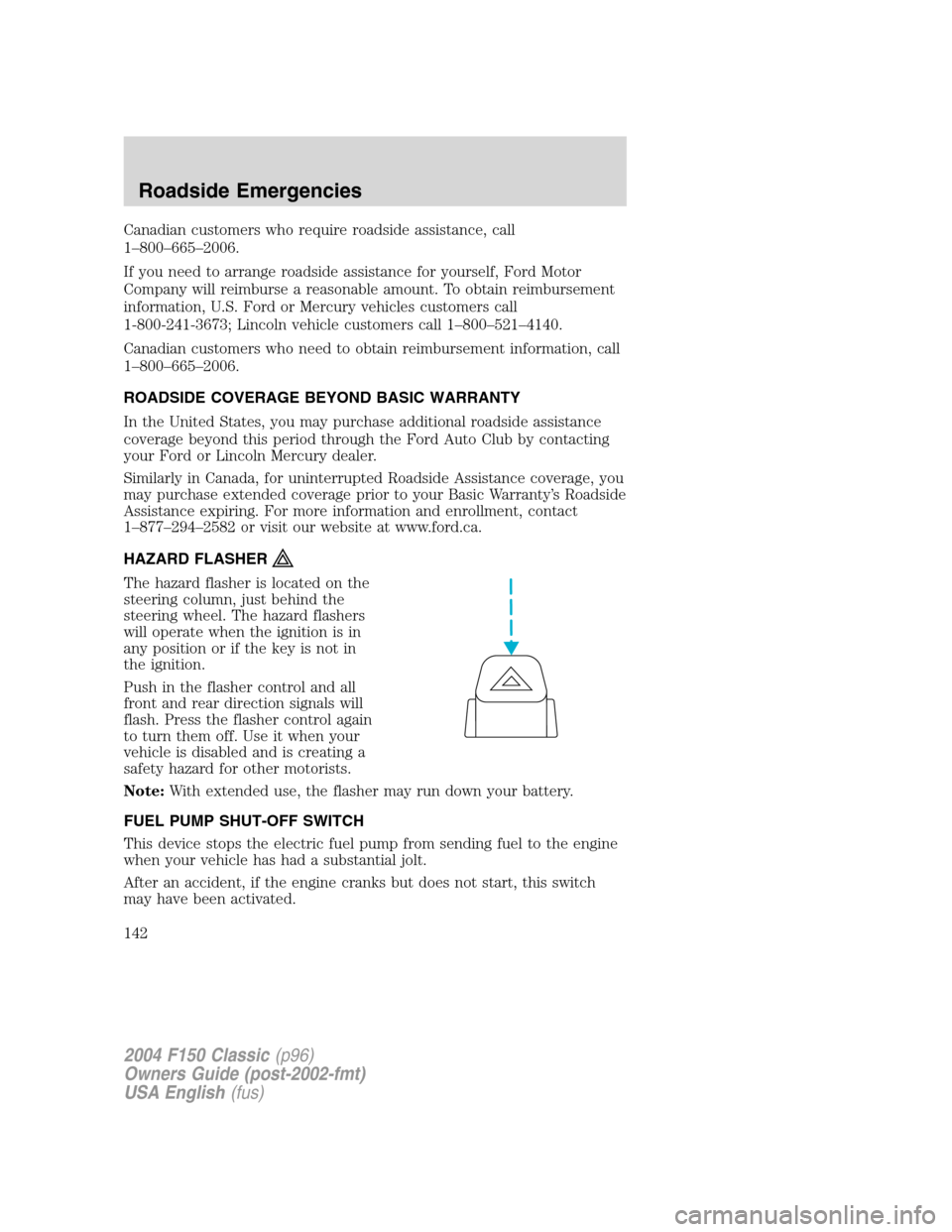
HAZARD FLASHER
The hazard flasher is located on the
steering column, just behind the
steering wheel. The hazard flashers
will operate when the ignition is in
any position or if the key is not in
the ignition.
Push in the flasher control and all
front and rear direction signals will
flash. Press the flasher control again
to turn them off. Use it when your
vehicle is disabled and is creating a
safety hazard for other motorists.
Note:With extended use, the flasher may run down your battery.
FUEL PUMP SHUT-OFF SWITCH
This device stops the electric fuel pump from sending fuel to the engine
when your vehicle has had a substantial jolt.
After an accident, if the engine cranks but does not start, this switch
may have been activated.
2004 F150 Classic(p96)
Owners Guide (post-2002-fmt)
USA English(fus)
Roadside Emergencies
142
Page 147 of 248
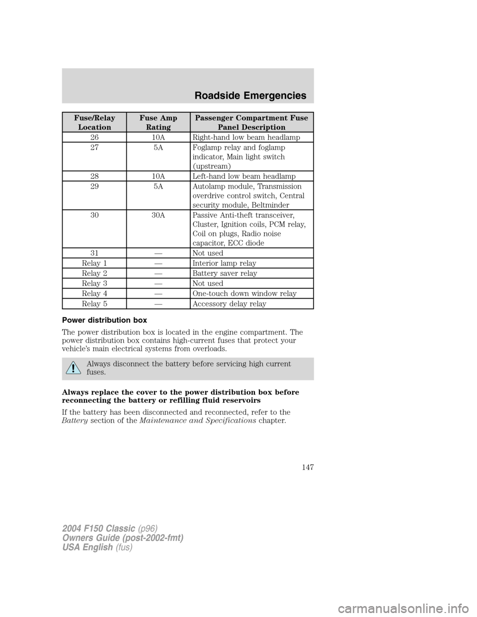
Fuse/Relay
LocationFuse Amp
RatingPassenger Compartment Fuse
Panel Description
26 10A Right-hand low beam headlamp
27 5A Foglamp relay and foglamp
indicator, Main light switch
(upstream)
28 10A Left-hand low beam headlamp
29 5A Autolamp module, Transmission
overdrive control switch, Central
security module, Beltminder
30 30A Passive Anti-theft transceiver,
Cluster, Ignition coils, PCM relay,
Coil on plugs, Radio noise
capacitor, ECC diode
31—Not used
Relay 1—Interior lamp relay
Relay 2—Battery saver relay
Relay 3—Not used
Relay 4—One-touch down window relay
Relay 5—Accessory delay relay
Power distribution box
The power distribution box is located in the engine compartment. The
power distribution box contains high-current fuses that protect your
vehicle’s main electrical systems from overloads.
Always disconnect the battery before servicing high current
fuses.
Always replace the cover to the power distribution box before
reconnecting the battery or refilling fluid reservoirs
If the battery has been disconnected and reconnected, refer to the
Batterysection of theMaintenance and Specificationschapter.
2004 F150 Classic(p96)
Owners Guide (post-2002-fmt)
USA English(fus)
Roadside Emergencies
147
Page 149 of 248
Fuse/Relay
LocationFuse Amp
RatingPower Distribution Box
Description
13 15A* A/C clutch
14—Not used
15—Not used
16 15A* Bi-fuel injector module, fuel
selector switch and alternative
fuel injectors (Bi-fuel vehicles
only)
17 2A* Speed control
18 15A* PCM, Fuel injectors, Fuel pump
relay, Mass air flow sensor
19 10A* Trailer/Camper adapter (right
stop/turn lamp)
20 10A* Trailer/Camper adapter (left
stop/turn lamp)
21—Not used
22—Not used
23 15A* HEGO sensor, Automatic
transmission
24—Not used
101 30A** Trailer tow battery charge
102 50/20A** Four-wheel Anti-lock Brake
System (4WABS)
module/Rear-wheel Anti-lock
Brake System (RABS) module,
Ignition switch
103 50A** Central junction box
104 30A** 4x4 shift motor & clutch
105 40A** Climate control front blower
106 20A** Intercooler pump (supercharged
engine only)
107—Not used
108 30A** Trailer tow electric brake
2004 F150 Classic(p96)
Owners Guide (post-2002-fmt)
USA English(fus)
Roadside Emergencies
149
Page 150 of 248
Fuse/Relay
LocationFuse Amp
RatingPower Distribution Box
Description
109—Not used
110 30A** Accessory delay relay
111 40A** Ignition switch battery feed (start
and run circuits)
112 30A** Drivers power seat, Adjustable
pedal switch
113 40A** Ignition switch battery feed (run
and accessory circuits)
114—Not used
115—Not used
116—Not used
117—Not used
118—Not used
201—Trailer tow park lamp relay
202—Front wiper run/park relay
203—Trailer tow backup lamp relay
204—A/C clutch relay
205—Horn relay
206—Fog lamp relay
207—Front washer pump relay
208—Intercooler pump relay
(supercharged engine only)
209—Front wiper HI/LO relay
301—Fuel pump relay
302—Trailer tow battery charge relay
303—Not used
304—PCM relay
305—Fuel pump HI/LO relay
(supercharged engine only)
306—Inertia switch relay (supercharged
engine only)
401—Not used
2004 F150 Classic(p96)
Owners Guide (post-2002-fmt)
USA English(fus)
Roadside Emergencies
150
Page 153 of 248
Location of the spare tire and tools
The spare tire and tools for your vehicle are stowed in the following
locations:
Tool Location
Spare tire Under the vehicle, just forward of
the rear bumper
Jack, lug nut wrench Under the seat on the passenger
side
Jack handle On top of the radiator support at
the front of the engine
compartment
Key, spare tire lock In the glove box
Removing the spare tire
1. If equipped with a two piece lug wrench, assemble the lug wrench as
shown in the illustration.
•To assemble, screw the parts
together. To disassemble,
unscrew.
2. Attach the spare tire lock key (A)
to the jack handle (B).
2004 F150 Classic(p96)
Owners Guide (post-2002-fmt)
USA English(fus)
Roadside Emergencies
153
Page 154 of 248
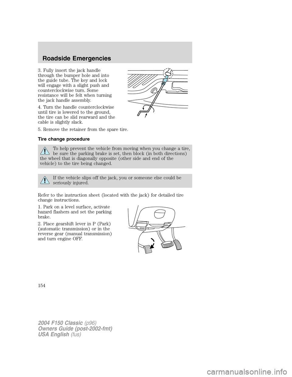
3. Fully insert the jack handle
through the bumper hole and into
the guide tube. The key and lock
will engage with a slight push and
counterclockwise turn. Some
resistance will be felt when turning
the jack handle assembly.
4. Turn the handle counterclockwise
until tire is lowered to the ground,
the tire can be slid rearward and the
cable is slightly slack.
5. Remove the retainer from the spare tire.
Tire change procedure
To help prevent the vehicle from moving when you change a tire,
be sure the parking brake is set, then block (in both directions)
the wheel that is diagonally opposite (other side and end of the
vehicle) to the tire being changed.
If the vehicle slips off the jack, you or someone else could be
seriously injured.
Refer to the instruction sheet (located with the jack) for detailed tire
change instructions.
1. Park on a level surface, activate
hazard flashers and set the parking
brake.
2. Place gearshift lever in P (Park)
(automatic transmission) or in the
reverse gear (manual transmission)
and turn engine OFF.
2004 F150 Classic(p96)
Owners Guide (post-2002-fmt)
USA English(fus)
Roadside Emergencies
154