Page 235 of 344
Load equalizing hitch
When hooking up a trailer using a load equalizing hitch, always use the
following procedure:
1. Park the unloaded vehicle on a level surface. With the ignition in the
ON position, apply the brake and place the gearshift lever in
(Overdrive) for 10 seconds, then return the gearshift lever to P (Park)
and release the brake. With the ignition still in the ON position, and all
doors closed, allow the vehicle to stand (without passengers) for several
minutes so that it can level.
2. Turn the air suspension (if equipped) control to OFF.
3. Measure the height of a reference point on the front and rear bumpers
at the center of the vehicle.
4. Attach the trailer to the vehicle and adjust the hitch equalizers so that
the front bumper height is within 0–13 mm (0.5 in) of the reference
point. After proper adjustment, the rear bumper should be no higher
than in Step 3.
5. Turn the air suspension (if equipped) control to ON.
Note:Adjusting an equalizing hitch so the rear bumper of the vehicle is
higher than it was unloaded will defeat the function of the load
equalizing hitch and may cause unpredictable handling.
Safety chains
Always connect the trailer’s safety chains to the frame or hook retainers
of the vehicle hitch. To connect the trailer’s safety chains, cross the
chains under the trailer tongue and allow slack for turning corners.
If you use a rental trailer, follow the instructions that the rental agency
gives to you.
Do not attach safety chains to the bumper.
Trailer brakes
Electric brakes and manual, automatic or surge-type trailer brakes are
safe if installed properly and adjusted to the manufacturer’s
specifications. The trailer brakes must meet local and Federal
regulations.
Do not connect a trailer’s hydraulic brake system directly to your
vehicle’s brake system. Your vehicle may not have enough
braking power and your chances of having a collision greatly increase.
2004 Expedition(exd)
Owners Guide (post-2002-fmt)
USA English(fus)
Driving
235
Page 242 of 344
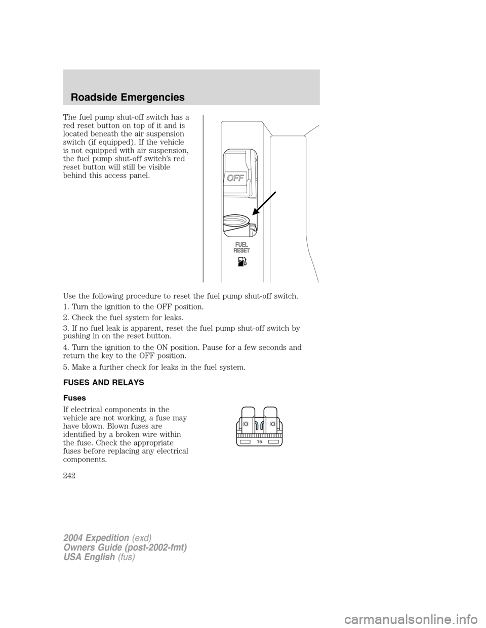
The fuel pump shut-off switch has a
red reset button on top of it and is
located beneath the air suspension
switch (if equipped). If the vehicle
is not equipped with air suspension,
the fuel pump shut-off switch’s red
reset button will still be visible
behind this access panel.
Use the following procedure to reset the fuel pump shut-off switch.
1. Turn the ignition to the OFF position.
2. Check the fuel system for leaks.
3. If no fuel leak is apparent, reset the fuel pump shut-off switch by
pushing in on the reset button.
4. Turn the ignition to the ON position. Pause for a few seconds and
return the key to the OFF position.
5. Make a further check for leaks in the fuel system.
FUSES AND RELAYS
Fuses
If electrical components in the
vehicle are not working, a fuse may
have blown. Blown fuses are
identified by a broken wire within
the fuse. Check the appropriate
fuses before replacing any electrical
components.
15
2004 Expedition(exd)
Owners Guide (post-2002-fmt)
USA English(fus)
Roadside Emergencies
242
Page 247 of 344
Fuse/Relay
LocationFuse Amp
RatingPassenger Compartment Fuse
Panel Description
11 10A* A/C compressor clutch relay, A/C
compressor clutch solenoid, Air
suspension compressor relay, 4x4
Integrated Wheel Ends (IWE)
solenoid
12 10A* Speed control servo, Speed
control relay
13 10A* Manual climate control mode
switch, Rear window defroster
relay coil, A/C refrigerant
containment switch, A/C
compressor thermistor, DEATC
control head, DEATC solenoids,
DEATC blower control, Trailer
tow battery charge relay coil
14 10A* Daytime Running Lamps (DRL)
ignition relay coil, Digital
Transmission Range Sensor
(DTRS) back-up lamps, Trailer
tow back-up lamps relay coil,
Electrochromatic mirror,
Navigation radio, Manual A/C
blend door actuator
15 5A* AdvanceTrac�switch, Instrument
cluster (Run/Start feed)
16 10A* ABS/AdvanceTrac�module
(Run/Start feed)
17 15A* Foglamps
2004 Expedition(exd)
Owners Guide (post-2002-fmt)
USA English(fus)
Roadside Emergencies
247
Page 248 of 344
Fuse/Relay
LocationFuse Amp
RatingPassenger Compartment Fuse
Panel Description
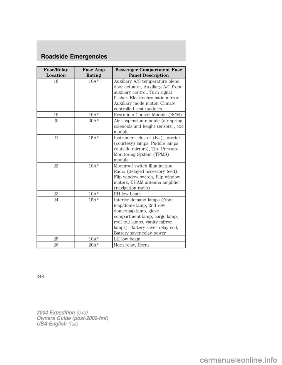
18 10A* Auxiliary A/C temperature blend
door actuator, Auxiliary A/C front
auxiliary control, Turn signal
flasher, Electrochromatic mirror,
Auxiliary mode motor, Climate
controlled seat modules
19 10A* Restraints Control Module (RCM)
20 30A* Air suspension module (air spring
solenoids and height sensors), 4x4
module
21 15A* Instrument cluster (B+), Interior
(courtesy) lamps, Puddle lamps
(outside mirrors), Tire Pressure
Monitoring System (TPMS)
module
22 10A* Moonroof switch illumination,
Radio (delayed accessory feed),
Flip window switch, Flip window
motors, EHAM antenna amplifier
(navigation radio)
23 10A* RH low beam
24 15A* Interior demand lamps (front
map/dome lamp, 2nd row
dome/map lamp, glove
compartment lamp, cargo lamp,
roof rail lamps, vanity mirror
lamps), Battery saver relay coil,
Battery saver relay power
25 10A* LH low beam
26 20A* Horn relay, Horns
2004 Expedition(exd)
Owners Guide (post-2002-fmt)
USA English(fus)
Roadside Emergencies
248
Page 249 of 344
Fuse/Relay
LocationFuse Amp
RatingPassenger Compartment Fuse
Panel Description
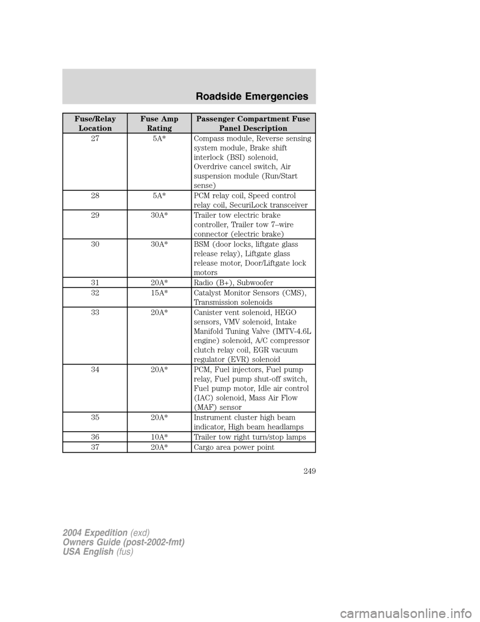
27 5A* Compass module, Reverse sensing
system module, Brake shift
interlock (BSI) solenoid,
Overdrive cancel switch, Air
suspension module (Run/Start
sense)
28 5A* PCM relay coil, Speed control
relay coil, SecuriLock transceiver
29 30A* Trailer tow electric brake
controller, Trailer tow 7–wire
connector (electric brake)
30 30A* BSM (door locks, liftgate glass
release relay), Liftgate glass
release motor, Door/Liftgate lock
motors
31 20A* Radio (B+), Subwoofer
32 15A* Catalyst Monitor Sensors (CMS),
Transmission solenoids
33 20A* Canister vent solenoid, HEGO
sensors, VMV solenoid, Intake
Manifold Tuning Valve (IMTV-4.6L
engine) solenoid, A/C compressor
clutch relay coil, EGR vacuum
regulator (EVR) solenoid
34 20A* PCM, Fuel injectors, Fuel pump
relay, Fuel pump shut-off switch,
Fuel pump motor, Idle air control
(IAC) solenoid, Mass Air Flow
(MAF) sensor
35 20A* Instrument cluster high beam
indicator, High beam headlamps
36 10A* Trailer tow right turn/stop lamps
37 20A* Cargo area power point
2004 Expedition(exd)
Owners Guide (post-2002-fmt)
USA English(fus)
Roadside Emergencies
249
Page 251 of 344
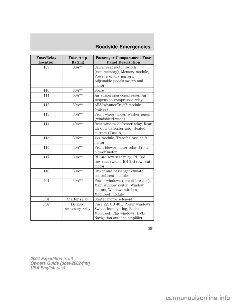
Fuse/Relay
LocationFuse Amp
RatingPassenger Compartment Fuse
Panel Description
109 30A** Driver seat motor switch
(non-memory), Memory module,
Power memory mirrors,
Adjustable pedals switch and
motor
110 30A** Spare
111 50A** Air suspension compressor, Air
suspension compressor relay
112 30A** ABS/AdvanceTrac�module
(valves)
113 30A** Front wiper motor, Washer pump
(windshield wash)
114 40A** Rear window defroster relay, Rear
window defroster grid, Heated
mirrors (Fuse 8)
115 30A** 4x4 module, Transfer case shift
motor
116 40A** Front blower motor relay, Front
blower motor
117 30A** RH 3rd row seat relay, RH 3rd
row seat switch, RH 3rd row seat
motor
118 30A** Driver and passenger climate
control seat module
401 30A** Power windows (circuit breaker),
Main window switch, Window
motors, Window switches,
Moonroof module
R01 Starter relay Starter motor solenoid
R02 Delayed
accessory relayFuse 22, CB 401, Power windows,
Switch backlighting, Radio,
Moonroof, Flip windows, DVD,
Navigation antenna amplifier
2004 Expedition(exd)
Owners Guide (post-2002-fmt)
USA English(fus)
Roadside Emergencies
251
Page 254 of 344
3. Unsnap the wheel lug nut wrench, jack extension and handle from the
plastic tray. Remove the jack and instruction sheet from the tray
assembly.
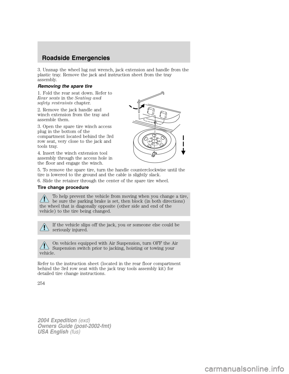
Removing the spare tire
1. Fold the rear seat down. Refer to
Rear seatsin theSeating and
safety restraintschapter.
2. Remove the jack handle and
winch extension from the tray and
assemble them.
3. Open the spare tire winch access
plug in the bottom of the
compartment located behind the 3rd
row seat, very close to the jack and
tools tray.
4. Insert the winch extension tool
assembly through the access hole in
the floor and engage the winch.
5. To remove the spare tire, turn the handle counterclockwise until the
tire is lowered to the ground and the cable is slightly slack.
6. Slide the retainer through the center of the spare tire wheel.
Tire change procedure
To help prevent the vehicle from moving when you change a tire,
be sure the parking brake is set, then block (in both directions)
the wheel that is diagonally opposite (other side and end of the
vehicle) to the tire being changed.
If the vehicle slips off the jack, you or someone else could be
seriously injured.
On vehicles equipped with Air Suspension, turn OFF the Air
Suspension switch prior to jacking, hoisting or towing your
vehicle.
Refer to the instruction sheet (located in the rear floor compartment
behind the 3rd row seat with the jack tray tools assembly kit) for
detailed tire change instructions.
2004 Expedition(exd)
Owners Guide (post-2002-fmt)
USA English(fus)
Roadside Emergencies
254
Page 257 of 344
•Never use the front or rear differential as a jacking point.
6. Remove the lug nuts with the lug wrench.
7. Replace the flat tire with the spare tire, making sure the valve stem is
facing outward. Reinstall the lug nuts until the wheel is snug against the
hub. Do not fully tighten the lug nuts until the wheel has been lowered.
8. Lower the wheel by turning the jack handle counterclockwise.
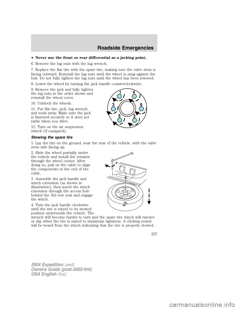
9. Remove the jack and fully tighten
the lug nuts in the order shown and
reinstall the wheel cover.
10. Unblock the wheels.
11. Put flat tire, jack, lug wrench
and tools away. Make sure the jack
is fastened securely so it does not
rattle when you drive.
12. Turn on the air suspension
switch (if equipped).
Stowing the spare tire
1. Lay the tire on the ground, near the rear of the vehicle, with the valve
stem side facing up.
2. Slide the wheel partially under
the vehicle and install the retainer
through the wheel center. After
doing so, pull on the cable to align
the components at the end of the
cable.
3. Assemble the jack handle and
winch extension (as shown in
illustration), then insert the winch
extension through the access hole
behind the 3rd row seat and engage
the winch.
4. Turn the jack handle clockwise
until the tire is raised to its stowed
position underneath the vehicle. The
wrench will become harder to turn and the spare tire winch will ratchet
or slip when the tire is raised to maximum tightness. A clicking sound
will be heard from the winch indicating that the tire is properly stowed.
2004 Expedition(exd)
Owners Guide (post-2002-fmt)
USA English(fus)
Roadside Emergencies
257