2004 DODGE TOWN AND COUNTRY transmission wiring
[x] Cancel search: transmission wiringPage 1 of 2585

GROUP TAB LOCATOR
Introduction
0Lubrication & Maintenance
2Suspension
3Differential & Driveline
5Brakes
5sBrakes
6Clutch
7Cooling
8AAudio
8BChime/Buzzer
8EElectronic Control Modules
8EsElectronic Control Modules
8FEngine Systems
8FsEngine Systems
8GHeated Systems
8HHorn
8IIgnition Control
8JInstrument Cluster
8LLamps
8MMessage Systems
8NPower Systems
8NsPower Systems
8ORestraints
8PSpeed Control
8QVehicle Theft Security
8RWipers/Washers
8WWiring
9Engine
9sEngine
11Exhaust System
13Frame & Bumpers
14Fuel System
19Steering
21Transmission/Transaxle
21sTransmission/Transaxle
22Tires/Wheels
22sTires/Wheels
23Body
24Heating & Air Conditioning
25Emissions Control
Component and System Index
Service Manual Comment Forms (Rear of Manual)
Page 152 of 2585

RED BRAKE WARNING INDICATOR LAMP
CONDITION POSSIBLE CAUSES CORRECTION
RED BRAKE WARNING
LAMP ON1. Parking brake lever not fully
released.1. Release parking brake lever.
2. Parking brake warning lamp
switch on parking brake lever.2. Inspect and replace switch as necessary.
3. Brake fluid level low in reservoir. 3. Fill reservoir. Check entire system for
leaks. Repair or replace as required.
4. Brake fluid level switch. 4. Disconnect switch wiring connector. If
lamp goes out, replace switch.
5. Mechanical instrument cluster
(MIC) problem.5. Refer to appropriate Diagnostic
information.
6. Amber ABS Warning Indicator
Lamp also illuminated.6. Refer to appropriate Diagnostic
information.
BRAKE NOISE
CONDITION POSSIBLE CAUSES CORRECTION
CLICK OR SQUAWK ON
PEDAL APPLICATION1. Brake lamp switch. 1. Replace switch.
2. Brake Transmission Shift Interlock
Linkage.2. Lubricate BTSI linkage.
3. Pedal pivot bushings 3. Lubricate pivot bushings. Replace if
necessary.
DISC BRAKE CHIRP 1. Excessive brake rotor runout. 1. Follow brake rotor diagnosis and testing.
Correct as necessary.
2. Lack of lubricant on brake caliper
slides.2. Lubricate brake caliper slides.
3. Caliper/shoes not fully seated. 3. Reseat caliper/shoes.
DISC BRAKE RATTLE OR
CLUNK1. Broken or missing anti-rattle
spring clips on shoes.1. Replace brake shoes.
2. Caliper guide pins/bolts loose. 2. Tighten guide pins/bolts.
DISC BRAKE SQUEAK AT
LOW SPEED (WHILE
APPLYING LIGHT BRAKE
PEDAL EFFORT)1. Brake shoe linings. 1. Replace brake shoes.
DRUM BRAKE CHIRP 1. Lack of lubricant on brake shoe
support plate where shoes ride.1. Lubricate shoe contact areas on brake
shoe support plates.
DRUM BRAKE CLUNK 1. Drum(s) have threaded machined
braking surface.1. Replace brake drums as necessary.
DRUM BRAKE HOWL OR
MOAN1. Lack of lubricant on brake shoe
support plate where shoes ride and
at the anchor.1. Lubricate shoe contact areas on brake
shoe support plates and at the anchor.
2. Rear brake shoes. 2. Replace rear brake shoes.
DRUM BRAKE SCRAPING
OR WHIRRING1. ABS wheel speed sensor or tone
wheel.1. Inspect, correct or replace faulty
component(s).
RSBRAKES - BASE5-5
BRAKES - BASE (Continued)
Page 247 of 2585

CAUTION
CAUTION: During service procedures, grease or
any other foreign material must be kept off brake
shoes and braking surfaces of brake rotor or drum,
and external surfaces of hub and bearing assembly.
CAUTION: Brake rotor and caliper handling must be
done in such a way as to avoid damage to the rotor,
especially the machined surfaces, and scratching or
nicking of the brake linings.
CAUTION: Only the recommended jacking or hoist-
ing procedures for this vehicle are to be usedwhenever it is necessary to lift a vehicle. Failure to
raise a vehicle utilizing the recommended lift points
can result in damage to the vehicle. (Refer to
LUBRICATION & MAINTENANCE/HOISTING - STAN-
DARD PROCEDURE)
DIAGNOSIS AND TESTING - BASE BRAKE
SYSTEM
NOTE: There are three diagnosis charts following
that cover the RED BRAKE WARNING INDICATOR
LAMP, BRAKE NOISE and OTHER BRAKE CONDI-
TIONS.
RED BRAKE WARNING INDICATOR LAMP
CONDITION POSSIBLE CAUSES CORRECTION
RED BRAKE WARNING
LAMP ON 1. Parking brake lever not fully
released. 1. Release parking brake lever.
2. Parking brake warning lamp
switch on parking brake lever. 2. Inspect and replace switch as necessary.
3. Brake fluid level low in reservoir. 3. Fill reservoir. Check entire system for leaks. Repair or replace as required.
4. Brake fluid level switch. 4. Disconnect switch wiring connector. If lamp goes out, replace switch.
5. Mechanical instrument cluster
(MIC) problem. 5. Refer to appropriate Diagnostic
information.
6. Amber ABS Warning Indicator
Lamp also illuminated. 6. Refer to appropriate Diagnostic
information.
BRAKE NOISE
CONDITION POSSIBLE CAUSES CORRECTION
CLICK OR SQUAWK ON
PEDAL APPLICATION 1. Brake lamp switch. 1. Replace switch.
2. Brake Transmission Shift Interlock
Linkage. 2. Lubricate BTSI linkage.
3. Pedal pivot bushings 3. Lubricate pivot bushings. Replace if necessary.
DISC BRAKE CHIRP 1. Excessive brake rotor runout. 1. Follow brake rotor diagnosis and testing. Correct as necessary.
2. Lack of lubricant on brake caliper
slides. 2. Lubricate brake caliper slides.
3. Caliper/shoes not fully seated. 3. Reseat caliper/shoes.
DISC BRAKE RATTLE OR
CLUNK 1. Broken or missing anti-rattle
spring clips on shoes. 1. Replace brake shoes.
2. Caliper guide pins/bolts loose. 2. Tighten guide pins/bolts.
5s - 4 BRAKESRS
BRAKES - BASE (Continued)
Page 367 of 2585

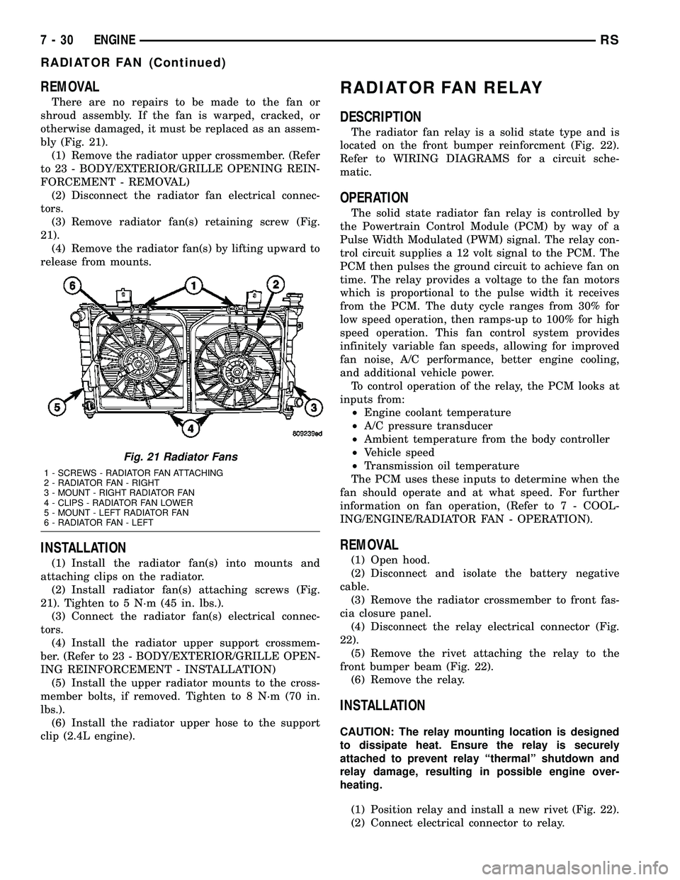
REMOVAL
There are no repairs to be made to the fan or
shroud assembly. If the fan is warped, cracked, or
otherwise damaged, it must be replaced as an assem-
bly (Fig. 21).
(1) Remove the radiator upper crossmember. (Refer
to 23 - BODY/EXTERIOR/GRILLE OPENING REIN-
FORCEMENT - REMOVAL)
(2) Disconnect the radiator fan electrical connec-
tors.
(3) Remove radiator fan(s) retaining screw (Fig.
21).
(4) Remove the radiator fan(s) by lifting upward to
release from mounts.
INSTALLATION
(1) Install the radiator fan(s) into mounts and
attaching clips on the radiator.
(2) Install radiator fan(s) attaching screws (Fig.
21). Tighten to 5 N´m (45 in. lbs.).
(3) Connect the radiator fan(s) electrical connec-
tors.
(4) Install the radiator upper support crossmem-
ber. (Refer to 23 - BODY/EXTERIOR/GRILLE OPEN-
ING REINFORCEMENT - INSTALLATION)
(5) Install the upper radiator mounts to the cross-
member bolts, if removed. Tighten to 8 N´m (70 in.
lbs.).
(6) Install the radiator upper hose to the support
clip (2.4L engine).
RADIATOR FAN RELAY
DESCRIPTION
The radiator fan relay is a solid state type and is
located on the front bumper reinforcment (Fig. 22).
Refer to WIRING DIAGRAMS for a circuit sche-
matic.
OPERATION
The solid state radiator fan relay is controlled by
the Powertrain Control Module (PCM) by way of a
Pulse Width Modulated (PWM) signal. The relay con-
trol circuit supplies a 12 volt signal to the PCM. The
PCM then pulses the ground circuit to achieve fan on
time. The relay provides a voltage to the fan motors
which is proportional to the pulse width it receives
from the PCM. The duty cycle ranges from 30% for
low speed operation, then ramps-up to 100% for high
speed operation. This fan control system provides
infinitely variable fan speeds, allowing for improved
fan noise, A/C performance, better engine cooling,
and additional vehicle power.
To control operation of the relay, the PCM looks at
inputs from:
²Engine coolant temperature
²A/C pressure transducer
²Ambient temperature from the body controller
²Vehicle speed
²Transmission oil temperature
The PCM uses these inputs to determine when the
fan should operate and at what speed. For further
information on fan operation, (Refer to 7 - COOL-
ING/ENGINE/RADIATOR FAN - OPERATION).
REMOVAL
(1) Open hood.
(2) Disconnect and isolate the battery negative
cable.
(3) Remove the radiator crossmember to front fas-
cia closure panel.
(4) Disconnect the relay electrical connector (Fig.
22).
(5) Remove the rivet attaching the relay to the
front bumper beam (Fig. 22).
(6) Remove the relay.
INSTALLATION
CAUTION: The relay mounting location is designed
to dissipate heat. Ensure the relay is securely
attached to prevent relay ªthermalº shutdown and
relay damage, resulting in possible engine over-
heating.
(1) Position relay and install a new rivet (Fig. 22).
(2) Connect electrical connector to relay.
Fig. 21 Radiator Fans
1 - SCREWS - RADIATOR FAN ATTACHING
2 - RADIATOR FAN - RIGHT
3 - MOUNT - RIGHT RADIATOR FAN
4 - CLIPS - RADIATOR FAN LOWER
5 - MOUNT - LEFT RADIATOR FAN
6 - RADIATOR FAN - LEFT
7 - 30 ENGINERS
RADIATOR FAN (Continued)
Page 387 of 2585

motors, and fuel pumps that have been found to be
potential sources of RFI or EMI.
OPERATION
There are two common strategies that can be used
to suppress Radio Frequency Interference (RFI) and
ElectroMagnetic Interference (EMI) radio noise. The
first suppression strategy involves preventing the
production of RFI and EMI electromagnetic signals
at their sources. The second suppression strategy
involves preventing the reception of RFI and EMI
electromagnetic signals by the audio system compo-
nents.
The use of braided ground straps in key locations
is part of the RFI and EMI prevention strategy.
These ground straps ensure adequate ground paths,
particularly for high current components such as
many of those found in the starting, charging, igni-
tion, engine control and transmission control sys-
tems. An insufficient ground path for any of these
high current components may result in radio noise
caused by induced voltages created as the high cur-
rent seeks alternative ground paths through compo-
nents or circuits intended for use by, or in close
proximity to the audio system components or circuits.
Preventing the reception of RFI and EMI is accom-
plished by ensuring that the audio system compo-
nents are correctly installed in the vehicle. Loose,
corroded or improperly soldered wire harness connec-
tions, improperly routed wiring and inadequate audio
system component grounding can all contribute to
the reception of RFI and EMI. A properly grounded
antenna body and radio chassis, as well as a shielded
antenna coaxial cable with clean and tight connec-
tions will each help reduce the potential for reception
of RFI and EMI.
REMOTE SWITCHES
DESCRIPTION
A remote radio control switch option is available on
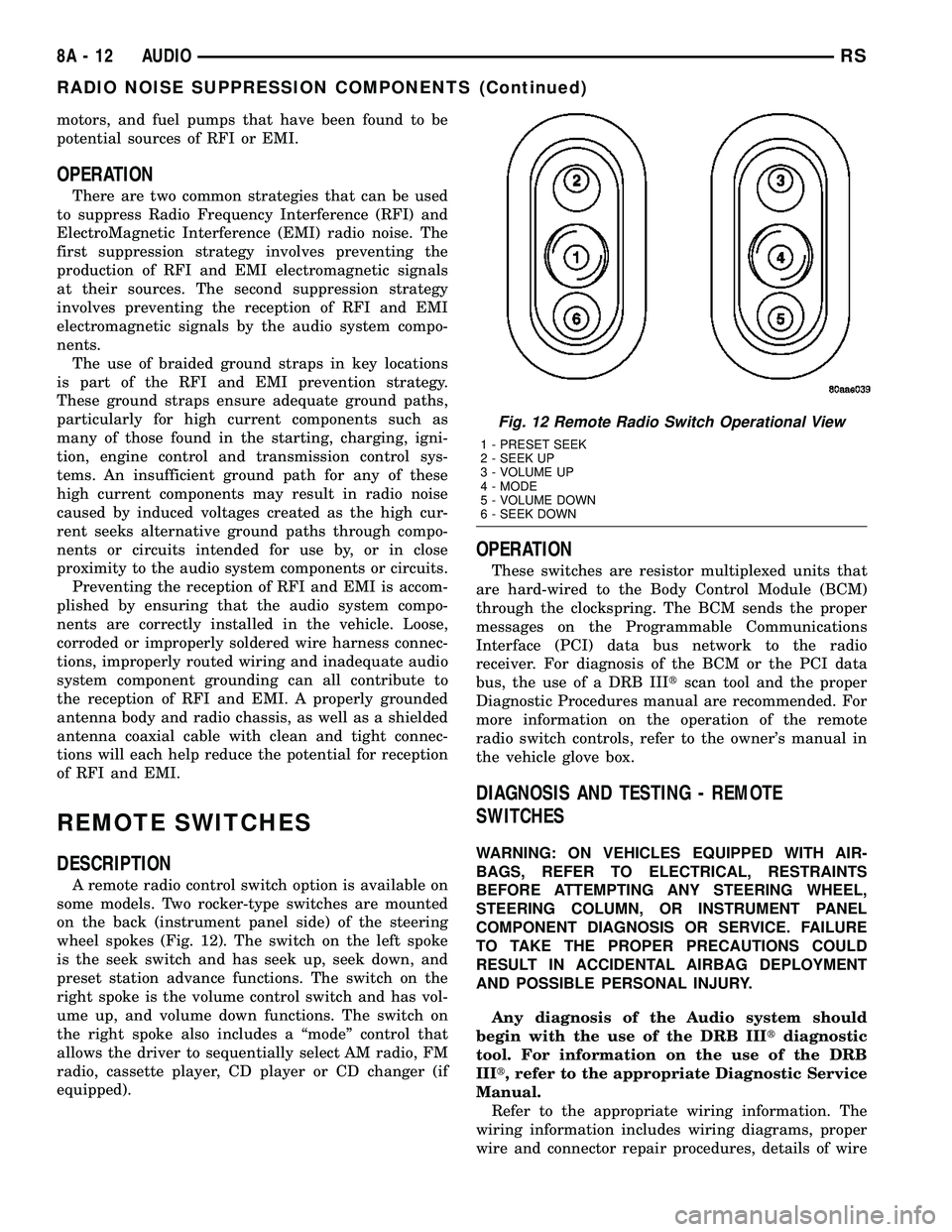
some models. Two rocker-type switches are mounted
on the back (instrument panel side) of the steering
wheel spokes (Fig. 12). The switch on the left spoke
is the seek switch and has seek up, seek down, and
preset station advance functions. The switch on the
right spoke is the volume control switch and has vol-
ume up, and volume down functions. The switch on
the right spoke also includes a ªmodeº control that
allows the driver to sequentially select AM radio, FM
radio, cassette player, CD player or CD changer (if
equipped).
OPERATION
These switches are resistor multiplexed units that
are hard-wired to the Body Control Module (BCM)
through the clockspring. The BCM sends the proper
messages on the Programmable Communications
Interface (PCI) data bus network to the radio
receiver. For diagnosis of the BCM or the PCI data
bus, the use of a DRB IIItscan tool and the proper
Diagnostic Procedures manual are recommended. For
more information on the operation of the remote
radio switch controls, refer to the owner's manual in
the vehicle glove box.
DIAGNOSIS AND TESTING - REMOTE
SWITCHES
WARNING: ON VEHICLES EQUIPPED WITH AIR-
BAGS, REFER TO ELECTRICAL, RESTRAINTS
BEFORE ATTEMPTING ANY STEERING WHEEL,
STEERING COLUMN, OR INSTRUMENT PANEL
COMPONENT DIAGNOSIS OR SERVICE. FAILURE
TO TAKE THE PROPER PRECAUTIONS COULD
RESULT IN ACCIDENTAL AIRBAG DEPLOYMENT
AND POSSIBLE PERSONAL INJURY.
Any diagnosis of the Audio system should
begin with the use of the DRB IIItdiagnostic
tool. For information on the use of the DRB
IIIt, refer to the appropriate Diagnostic Service
Manual.
Refer to the appropriate wiring information. The
wiring information includes wiring diagrams, proper
wire and connector repair procedures, details of wire
Fig. 12 Remote Radio Switch Operational View
1 - PRESET SEEK
2 - SEEK UP
3 - VOLUME UP
4 - MODE
5 - VOLUME DOWN
6 - SEEK DOWN
8A - 12 AUDIORS
RADIO NOISE SUPPRESSION COMPONENTS (Continued)
Page 403 of 2585

INSTALLATION
(1) Connect the module wire harness connectors.
(2) Snap the module on the seat cushion pan.
(3) Install the appropriate front seat in the vehicle
(Refer to 23 - BODY/SEATS/SEAT - INSTALLA-
TION).
(4) Connect and isolate the negative battery cable.
MEMORY SEAT/MIRROR
MODULE
DESCRIPTION
Vehicles equipped with the memory seat/mirror
option, utilize a memory module located under the
drivers front seat. This module is basically wired in-
line between the power seat switch and the power
seat track/adjuster motors, or in-line between the
power mirror switch and the power side view mir-
ror(s) motor(s). The MSMM contains a central pro-
cessing unit that communicates with other modules
on the Programmable Communications Interface
(PCI) data bus network.
The Memory Seat/Mirror Module (MSMM) receives
hard wired inputs from the driver power seat switch
and the potentiometers on each of the driver side
power seat track motors, or from the power mirror
switch and the potentiometers on the side view mir-
ror. The MSMM receives messages over the PCI data
bus from the Body Control Module (BCM) (memory
switch status), the Powertrain Control Module (PCM)
(vehicle speed status). The MSMM will prevent the
seat memory recall function from being initiated if
the driver side seat belt is buckled, if the transmis-
sion gear selector lever is not in the Park or Neutral
positions, or if the vehicle is moving.
For diagnosis of the MSMM or the PCI data bus, a
DRB IIItscan tool and the proper Diagnostic Proce-
dures manual are recommended. The MSMM cannot
be repaired and, if faulty or damaged, it must be
replaced. Refer toMemory Systemin the Power
Seat or Power Mirror section of this manual for more
information on the memory system option.
OPERATION
When memory system operation is requested
(depressing of the memory switch), a resistor multi-
plexed signal is sent from the memory switch to the
body control module (BCM). The body control module
will then send the appropriate signals out to the
memory/mirror seat module, the memory/mirror seat
module then applies the voltage supply to the power
seat track or side-view mirror if the proper require-
ments are met. The vehicle speed must equal zero
and the transmission must be in park or neutral in
order for the memory system to function.
DIAGNOSIS AND TESTING - MEMORY
SEAT/MIRROR MODULE
Visually inspect the related wiring harness connec-
tors. Look for broken, bent, pushed out, or corroded
terminals. If any of the above conditions are present,
repair as necessary. If not, use a DRB IIItscan tool
and the proper Diagnostic Procedures Manual to test
the memory/mirror seat module. For complete circuit
diagrams, refer toWiring Diagrams.
REMOVAL
(1) Disconnect and isolate the battery negative
cable.
(2) Remove the driver side front bucket seat
retaining nuts from under the vehicle (Refer to 23 -
BODY/SEATS/SEAT - REMOVAL).
(3) Lift the drivers seat up and out of the mount-
ing holes in the floor pan and lay the seat rearward
to access the module located under the seat. It is not
necessary to disconnect the seat electrical, just use
care not to damage the wiring by over-extending.
(4) Disconnect the memory/mirror seat module
electrical connectors. Depress the retaining tab and
pull straight apart.
(5) Remove the module retaining bolts and remove
the module from the bracket.
INSTALLATION
(1) Position and install the module retaining bolts.
(2) Connect the memory/mirror seat module elec-
trical connectors.
(3) Position the drivers seat in the mounting holes
in the floor pan.
(4) Install the driver side front bucket seat retain-
ing nuts from under the vehicle (Refer to 23 - BODY/
SEATS/SEAT - INSTALLATION).
(5) Connect the battery negative cable.
POWER LIFTGATE CONTROL
MODULE
DESCRIPTION
Vehicles equipped with a power liftgate (PLG) uti-
lize a PLG control module. This module is located on
the vehicles left side D-pillar just below the motor
assembly (Fig. 8) and contains a microprocessor,
which is used to communicate to the vehicles body
control module. The PLG control module receives and
monitors logic inputs from all the PLG system
switches except for the outside handle switch. This
module also contains the software technology to
detect liftgate obstructions and stop and/or reverse
the door accordingly.
8E - 10 ELECTRONIC CONTROL MODULESRS
HEATED SEAT MODULE (Continued)
Page 406 of 2585

fuel pump and the heating element in each oxygen
sensor.
The PCM contains a voltage converter that
changes battery voltage to a regulated 8.0 volts. The
8.0 volts power the camshaft position sensor, crank-
shaft position sensor and vehicle speed sensor. The
PCM also provides a 5.0 volts supply for the engine
coolant temperature sensor, intake air temperature
sensor, manifold absolute pressure sensor and throt-
tle position sensor.
The PCM engine control strategy prevents reduced
idle speeds until after the engine operates for 320 km
(200 miles). If the PCM is replaced after 320 km (200
miles) of usage, update the mileage in new PCM. Use
the DRBIIItscan tool to change the mileage in the
PCM. Refer to the appropriate Powertrain Diagnostic
Manual and the DRBIIItscan tool.
TRANSMISSION CONTROL (2.4L MODELS ONLY)
CLUTCH VOLUME INDEX (CVI)
An important function of the PCM is to monitor
Clutch Volume Index (CVI). CVIs represent the vol-
ume of fluid needed to compress a clutch pack.
The PCM monitors gear ratio changes by monitor-
ing the Input and Output Speed Sensors. The Input,
or Turbine Speed Sensor sends an electrical signal to
the PCM that represents input shaft rpm. The Out-
put Speed Sensor provides the PCM with output
shaft speed information.
By comparing the two inputs, the PCM can deter-
mine transaxle gear ratio. This is important to the
CVI calculation because the PCM determines CVIs
by monitoring how long it takes for a gear change to
occur (Fig. 10).
Gear ratios can be determined by using the DRB
Scan Tool and reading the Input/Output Speed Sen-
sor values in the ªMonitorsº display. Gear ratio can
be obtained by dividing the Input Speed Sensor value
by the Output Speed Sensor value.
For example, if the input shaft is rotating at 1000
rpm and the output shaft is rotating at 500 rpm,
then the PCM can determine that the gear ratio is
2:1. In direct drive (3rd gear), the gear ratio changesto 1:1. The gear ratio changes as clutches are applied
and released. By monitoring the length of time it
takes for the gear ratio to change following a shift
request, the PCM can determine the volume of fluid
used to apply or release a friction element.
The volume of transmission fluid needed to apply
the friction elements are continuously updated for
adaptive controls. As friction material wears, the vol-
ume of fluid need to apply the element increases.
Certain mechanical problems within the clutch
assemblies (broken return springs, out of position
snap rings, excessive clutch pack clearance, improper
assembly, etc.) can cause inadequate or out-of-range
clutch volumes. Also, defective Input/Output Speed
Sensors and wiring can cause these conditions. The
following chart identifies the appropriate clutch vol-
umes and when they are monitored/updated:
CLUTCH VOLUMES
ClutchWhen Updated
Proper Clutch
Volume
Shift Sequence Oil Temperature Throttle Angle
L/R2-1 or 3-1 coast
downshift>70É <5É 35to83
2/4 1-2 shift
> 110É5 - 54É20 to 77
OD 2-3 shift 48 to 150
UD 4-3 or 4-2 shift > 5É 24 to 70
Fig. 10 Example of CVI Calculation
1 - OUTPUT SPEED SENSOR
2 - OUTPUT SHAFT
3 - CLUTCH PACK
4 - SEPARATOR PLATE
5 - FRICTION DISCS
6 - INPUT SHAFT
7 - INPUT SPEED SENSOR
8 - PISTON AND SEAL
RSELECTRONIC CONTROL MODULES8E-13
POWERTRAIN CONTROL MODULE (Continued)
Page 414 of 2585

In addition to monitoring inputs and controlling
outputs, the TCM has other important responsibili-
ties and functions:
²Storing and maintaining Clutch Volume Indices
(CVI)
²Storing and selecting appropriate Shift Sched-
ules
²System self-diagnostics
²Diagnostic capabilities (with DRB scan tool)
CLUTCH VOLUME INDEX (CVI)
An important function of the TCM is to monitor
Clutch Volume Index (CVI). CVIs represent the vol-
ume of fluid needed to compress a clutch pack.
The TCM monitors gear ratio changes by monitor-
ing the Input and Output Speed Sensors. The Input,
or Turbine Speed Sensor sends an electrical signal to
the TCM that represents input shaft rpm. The Out-
put Speed Sensor provides the TCM with output
shaft speed information.
By comparing the two inputs, the TCM can deter-
mine transaxle gear ratio. This is important to the
CVI calculation because the TCM determines CVIs
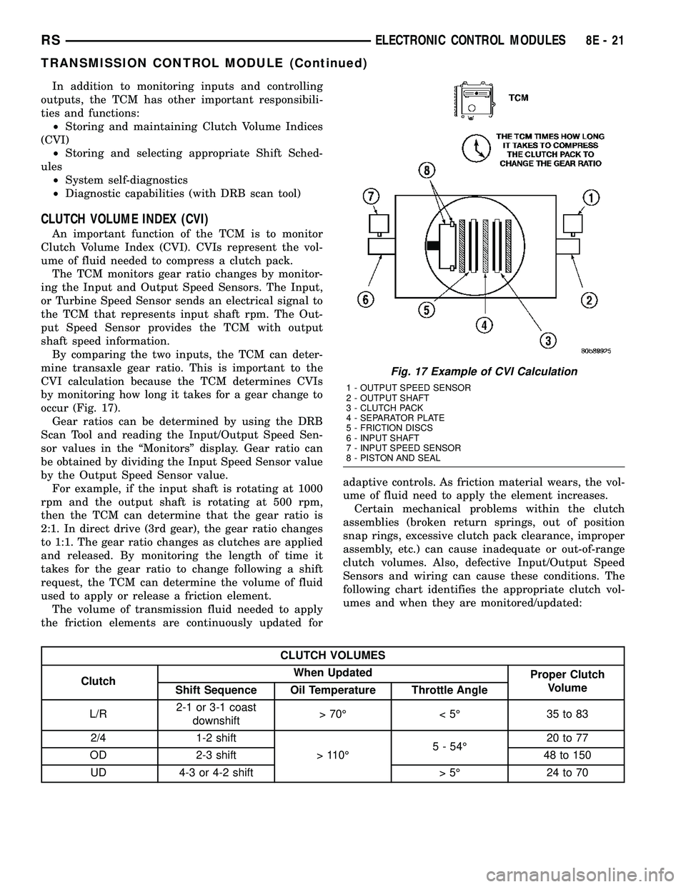
by monitoring how long it takes for a gear change to
occur (Fig. 17).
Gear ratios can be determined by using the DRB
Scan Tool and reading the Input/Output Speed Sen-
sor values in the ªMonitorsº display. Gear ratio can
be obtained by dividing the Input Speed Sensor value
by the Output Speed Sensor value.
For example, if the input shaft is rotating at 1000
rpm and the output shaft is rotating at 500 rpm,
then the TCM can determine that the gear ratio is
2:1. In direct drive (3rd gear), the gear ratio changes
to 1:1. The gear ratio changes as clutches are applied
and released. By monitoring the length of time it
takes for the gear ratio to change following a shift
request, the TCM can determine the volume of fluid
used to apply or release a friction element.
The volume of transmission fluid needed to apply
the friction elements are continuously updated foradaptive controls. As friction material wears, the vol-
ume of fluid need to apply the element increases.
Certain mechanical problems within the clutch
assemblies (broken return springs, out of position
snap rings, excessive clutch pack clearance, improper
assembly, etc.) can cause inadequate or out-of-range
clutch volumes. Also, defective Input/Output Speed
Sensors and wiring can cause these conditions. The
following chart identifies the appropriate clutch vol-
umes and when they are monitored/updated:
CLUTCH VOLUMES
ClutchWhen Updated
Proper Clutch
Volume
Shift Sequence Oil Temperature Throttle Angle
L/R2-1 or 3-1 coast
downshift>70É <5É 35to83
2/4 1-2 shift
> 110É5 - 54É20 to 77
OD 2-3 shift 48 to 150
UD 4-3 or 4-2 shift > 5É 24 to 70
Fig. 17 Example of CVI Calculation
1 - OUTPUT SPEED SENSOR
2 - OUTPUT SHAFT
3 - CLUTCH PACK
4 - SEPARATOR PLATE
5 - FRICTION DISCS
6 - INPUT SHAFT
7 - INPUT SPEED SENSOR
8 - PISTON AND SEAL
RSELECTRONIC CONTROL MODULES8E-21
TRANSMISSION CONTROL MODULE (Continued)